 |
|||
|
|
|||
|
|
|||
| ||||||||||
|
|
 TM 5-2410-237-23
BLADE TILT AND RIPPER PILOT VALVE ASSEMBLY REPLACEMENT - CONTINUED
0204 00
INSTALLATION - CONTINUED
6.
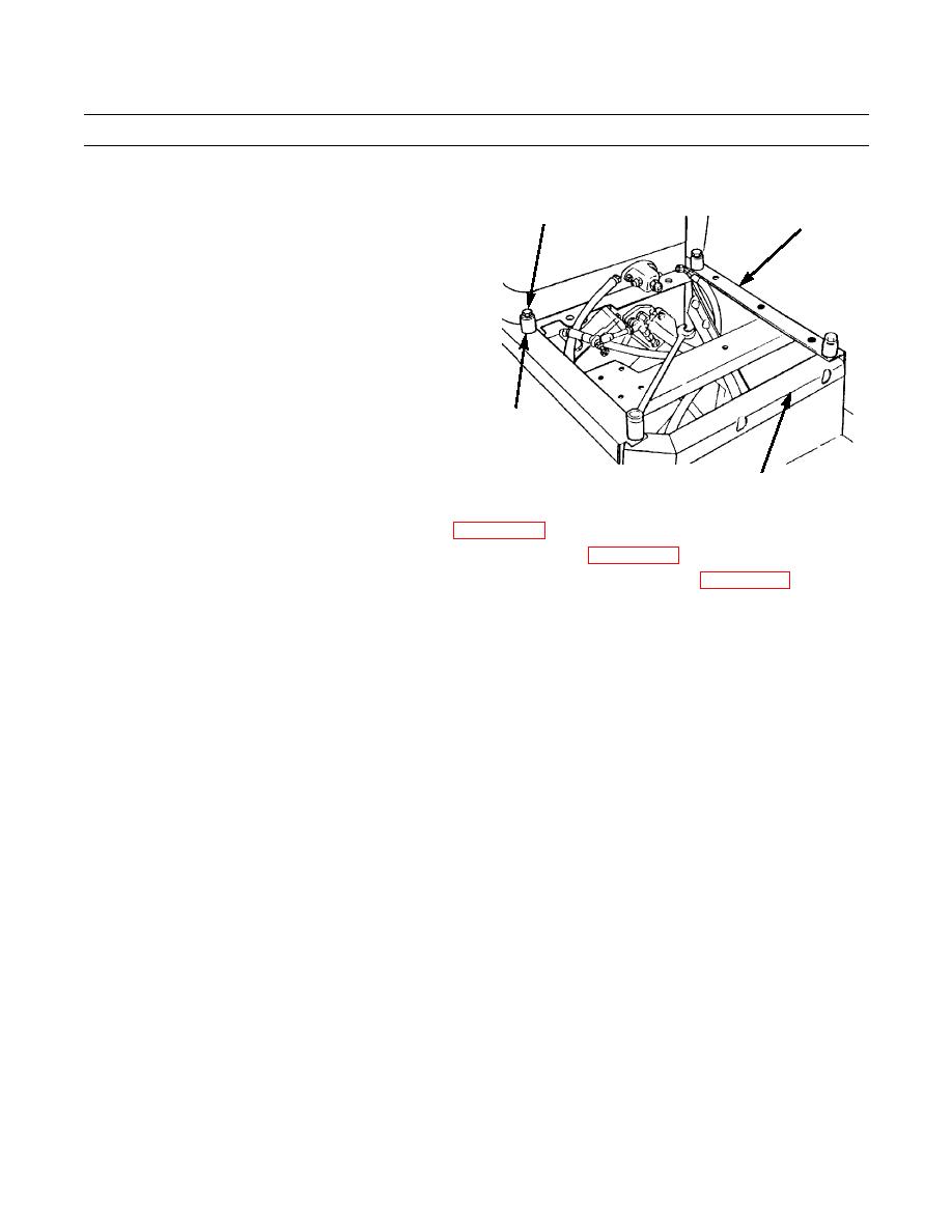
Install frame (4) to control housing (5) with four
1,2
capscrews (1), washers (2) and spacers (3).
4
3
387-603
5
7.
Connect blade control linkage to blade tilt pilot valve (WP 0207 00).
8.
If equipped with ripper, connect ripper control linkage to ripper pilot valve (WP 0208 00).
9.
Check machine oil level in hydraulic tank. Refill tank and bleed air from system, as required (WP 0241 00).
10.
Operate machine and check blade and ripper for proper operation and leaks (TM 5-2410-237-10).
END OF WORK PACKAGE
0204 00-5
|
|
Privacy Statement - Press Release - Copyright Information. - Contact Us |