 |
|||
|
|
|||
|
Page Title:
RELIEF VALVE SETTING ADJUSTMENT |
|
||
| ||||||||||
|
|
 TM 5-2410-237-23
BLADE CONTROL VALVE REPLACEMENT - CONTINUED
0201 00
RELIEF VALVE SETTING ADJUSTMENT
WARNING
Do NOT remove hydraulic tank filler cap or disconnect or remove any hydraulic system line or fitting
unless hydraulic system pressure has been relieved. Hydraulic system pressure can be over 2500 psi
(17,237 kPa), even with engine and pump OFF. To relieve pressure, lower all hydraulic attachments to
the ground and shut down engine. Move control levers through all operating positions, then SLOWLY
loosen hydraulic tank filler cap. After maintenance, tighten all connections before applying pressure.
Escaping hydraulic fluid under pressure can penetrate the skin, causing serious injury or death.
At operating temperature hydraulic oil is hot. Allow hydraulic oil to cool before removing any compo-
nent. Failure to do so could result in injury.
1.
Relieve hydraulic system pressure (WP 0241 00).
WARNING
Personal injury can result when relief valve plugs are removed. Remove plugs slowly to release spring ten-
sion.
NOTE
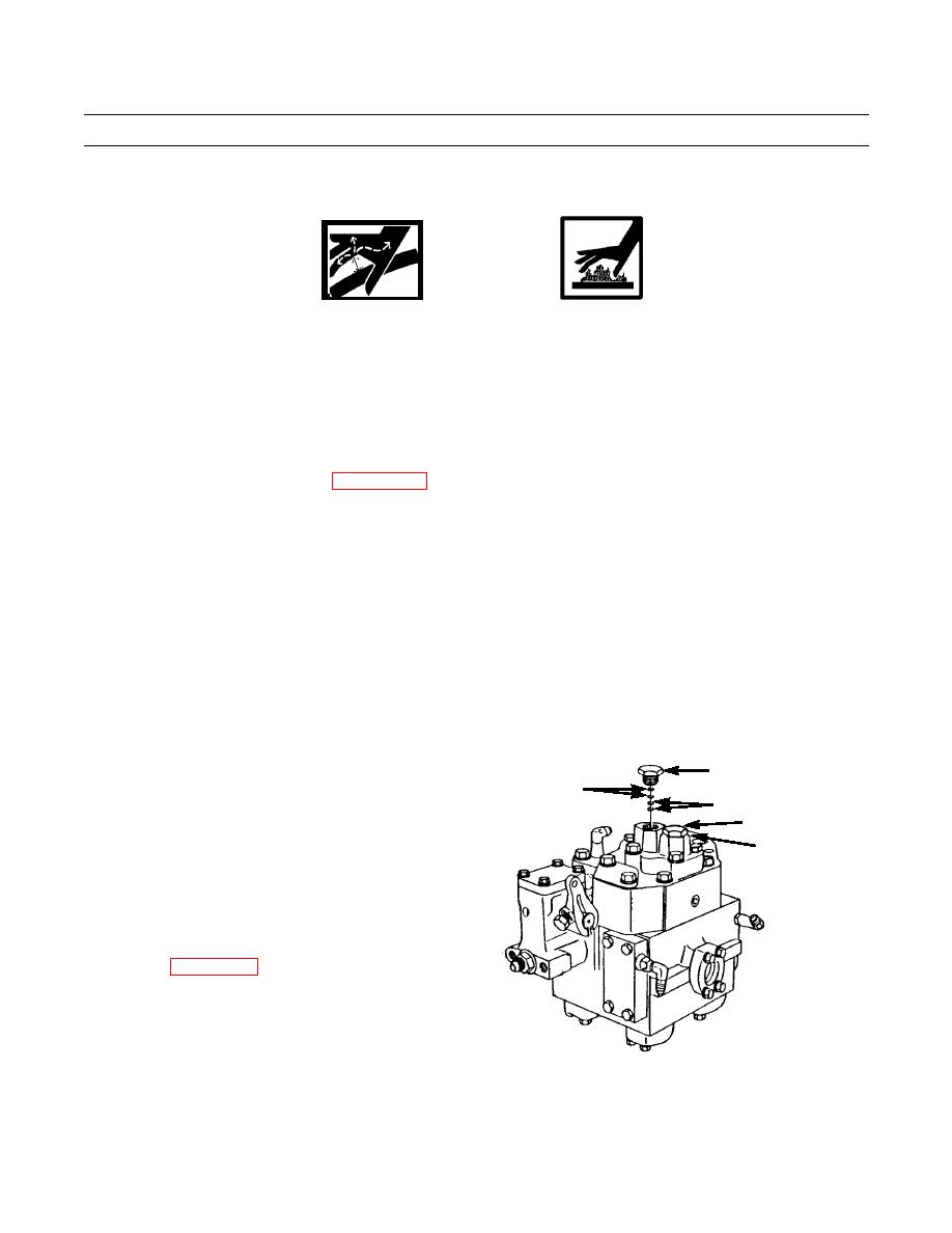
Plug (26) for bulldozer blade lift and ripper lift is stamped "15 500 KPA". Plug (27) for blade tilt is
stamped "16 900 KPA."
If tests indicate one or both relief valves need adjustment, perform the following.
2.
Slowly remove plug(s) (26 and 27). Remove O-rings
(28) from plugs and discard.
26
29
3.
Add shims (29) to increase relief valve setting or
(15 500 KPA)
remove shims to decrease setting:
27 (16 900) KPA)
a. One 0.005 in. shim will change relief pressure by
28
35 psi (240 kPa).
b. One 0.048 in. shim will change relief pressure by
335 psi (2310 kPa).
4.
Install new O-rings (28) and plug(s) (26 and 27).
Tighten to 80 lb-ft (108 Nm).
5.
Repeat hydraulic system tests to ensure settings are
correct (WP 0227 00).
387-970
END OF WORK PACKAGE
0201 00-6
|
|
Privacy Statement - Press Release - Copyright Information. - Contact Us |