 |
|||
|
|
|||
|
|
|||
| ||||||||||
|
|
 TM 5-2410-237-23
BLADE CONTROL VALVE REPLACEMENT - CONTINUED
0201 00
INSTALLATION - CONTINUED
9.
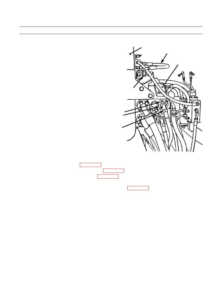
Install all hydraulic lines on blade control valve (1)
2
and tank (2) using one of the following procedures:
9
a.
For hydraulic lines with flange fittings: Install
line (6) and new O-ring (7) to blade control valve
1
(1)with two split flanges (5), four capscrews (3)
and four washers (4).
b.
For hydraulic lines with connector fittings:
Install fitting and new O-ring (10) to blade con-
trol valve (1). Install end of line (9) to proper
location and tighten connector (8).
8,10
3,4
5,7
6
387-588
10.
Install blade and ripper pilot valves (WP 0204 00).
11.
Install hydraulic tank mounting brackets and plates (WP 0156 00).
12.
Refill hydraulic tank and bleed air from system (WP 0225 00).
13.
Operate machine and check for proper operation with blade control levers in all operating positions. Check for leaks.
14.
Perform hydraulic system tests to ensure valve is operating properly (WP 0227 00).
15.
If tests indicate incorrect relief valve setting, adjust IAW Relief Valve Setting Adjustment in this work package.
0201 00-5
|
|
Privacy Statement - Press Release - Copyright Information. - Contact Us |