 |
|||
|
|
|||
|
|
|||
| ||||||||||
|
|
 TM 5-2410-237-23
HYDRAULIC PUMP REPAIR - CONTINUED
0200 00
ASSEMBLY - CONTINUED
7.
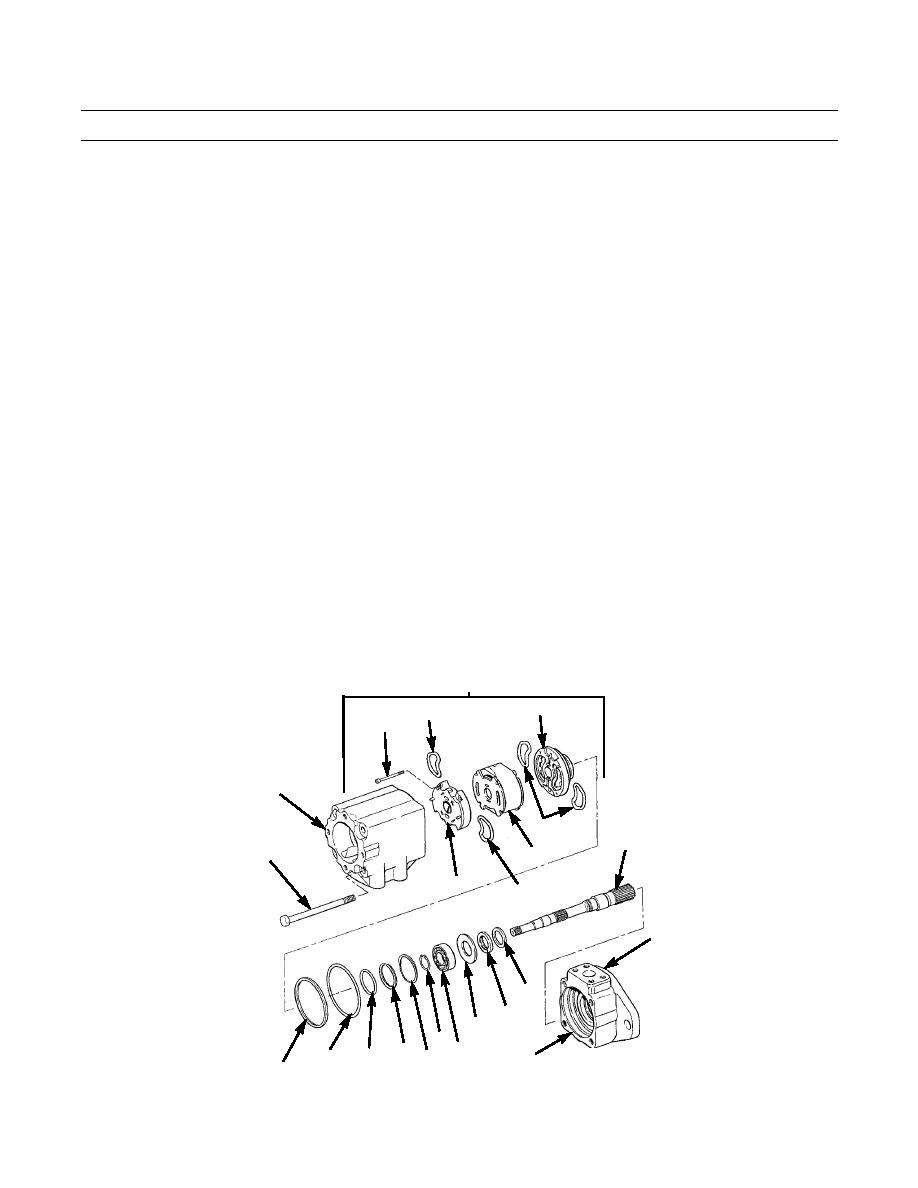
Install new O-ring (37) in pump body (3).
NOTE
Seals (44 and 46) are two-piece seals. Ensure that preformed packing seal is in plastic seal before seals are
installed.
8.
Install two new seals (46) with preformed packing in contact with end plate (45).
9.
Install two new seals (44) with preformed packing in contact with plate (41).
10.
Position plates (41 and 45) on plate (43) and loosely install four capscrews (42) in holes nearest arrows that are the same
direction as arrow on plate (41). These arrows show direction of pump rotation and must be assembled with arrows in
same direction.
11.
Install new O-ring (40) and new preformed packing (39) on sub-assembly (38), with O-ring installed toward pressure
source.
12.
Install sub-assembly (38) on pump body (3), with sub-assembly positioned so pins in plate (41) are in alignment with
mounting holes of center cover (2).
13.
Tighten four capscrews (42).
14.
Install new seal (36).
15.
Align pins in plate of sub-assembly (38) with holes in center cover (2). Install pump body (3) and sub-assembly in cen-
ter cover according to markings made at disassembly.
16.
Install four capscrews (35) and tighten capscrews to 70 lb-ft (95 Nm).
38
45
44
42
2
46
48
35
43
41
44
3
53
52
51
47
39 49 50
40
37
387-499
54 (HIDDEN)
36
0200 00-7
|
|
Privacy Statement - Press Release - Copyright Information. - Contact Us |