 |
|||
|
|
|||
|
|
|||
| ||||||||||
|
|
 TM 5-2410-237-23
WINCH CONTROL LEVER AND LINKAGE ADJUSTMENT - CONTINUED
0182 00
ADJUSTMENT - CONTINUED
14.
Start engine. Adjust control cable (20) until pressure at brake tap is 185 +/- 5 psi (1270 +/- 35 kPa).
15.
Move control lever (13) into clip (24). If control lever is not held by clip, adjust control cable (20) until control lever is
held. At this time, pressure at brake pressure tap must be not less than 160 psi (1100 kPa).
16.
Tighten nut (22) securely against rod end (19).
17.
Install rod end (19) on bellcrank (21) with capscrew (17) and new self-locking nut (18).
18.
Do not tighten bellcrank mounting nut. Install on threads until there is a minimum amount of free movement in
bellcrank (21) and bellcrank is free to turn.
19.
Move control lever (13) to all positions. Ensure that threads on control cables (9 and 20) do not come in contact with
rubber seals. If threads come in contact with rubber seals, adjust cables again.
20.
Install guide (11) to cover (12) with four capscrews (10).
21.
Remove pressure gage from brake pressure tap (23).
1,3
2,3
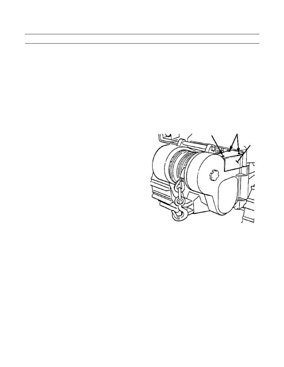
22.
Install cover (4) with two capscrews (1), capscrews (2)
and four new lockwashers (3).
4
23.
Operate winch and check for proper operation (TM 5-
2410-237-10).
387-387
END OF WORK PACKAGE
0182 00-3
|
|
Privacy Statement - Press Release - Copyright Information. - Contact Us |
