 |
|||
|
|
|||
|
|
|||
| ||||||||||
|
|
 TM 5-2410-237-23
STEERING CLUTCH CONTROL VALVE MAINTENANCE - CONTINUED
0154 00
ASSEMBLY - CONTINUED
23.
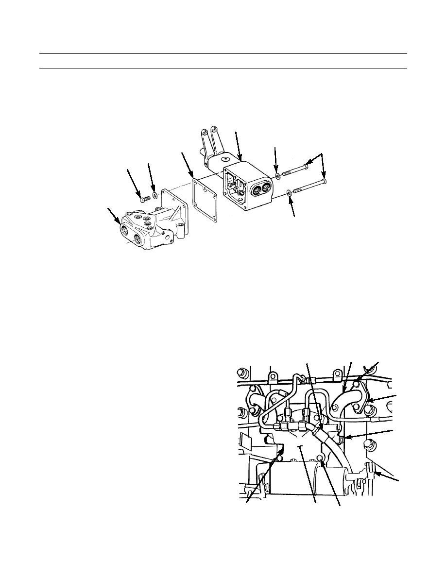
Position new gasket (35) on mating surface of spool housing (31) and position spool housing to lever housing (32).
24.
Install two washers (34) and capscrews (33) through lever housing (32) into spool housing (31).
25.
Install three washers (30) and capscrews (29) to secure two housings.
32
34
35
33
30
29
31
34
387-738
INSTALLATION
CAUTION
Care should be taken not to contaminate hydraulic system during installation of hydraulic lines. Dirt and
foreign substances should be removed from surrounding area before lines are installed.
NOTE
Apply a light film of clean oil to new O-rings prior to installation.
1.
Position three new O-rings (28) on bevel of gear case.
20
25 (HIDDEN)
21,22,23
2.
Position control valve (6) on gear case. Ensure O-rings
(28) are properly seated.
3.
Install four new lockwashers (27) and capscrews (26)
24
to secure control valve (6) to gear case.
4.
Install new O-rings (24 and 25) in flange at each end
of elbow (20).
5.
Install one end of elbow (20) on control valve (6) with
18,19
two new lockwashers (19) and capscrews (18).
6.
Install other end of elbow (20) with two washers (23),
new lockwashers (22) and capscrews (21).
7.
Repeat steps 4-6 for elbow on other side of control
valve (6).
17
387-708
28 (HIDDEN)
6
26,27
0154 00-9
|
|
Privacy Statement - Press Release - Copyright Information. - Contact Us |