 |
|||
|
|
|||
|
|
|||
| ||||||||||
|
|
 TM 5-2410-237-23
STEERING BRAKE HYDRAULIC CONTROL ASSEMBLY MAINTENANCE - CONTINUED
0151 00
DISASSEMBLY - CONTINUED
WARNING
Plunger assembly (65), lever (66) and cover (57) are under spring pressure. Use caution when removing
these parts to prevent personal injury or damaged or lost parts.
To prevent injury or lost parts, remove cover (57) and install it backwards with two capscrews and
leave in place until ready to remove plunger assembly (65).
7.
Use a large screwdriver to compress plunger assembly (65) and place capscrew between plunger assembly and mount-
ing lip of cover (57) inside hydraulic control (12), to keep pressure off lever (66).
8.
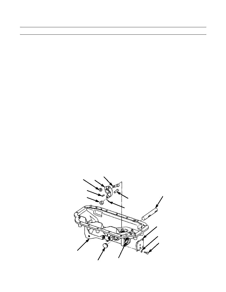
Remove four capscrews (67), lockwashers (68) and cover (57) from end of hydraulic control (12). Use two capscrews
(67) to reinstall cover backwards over opening to prevent plunger assembly (65) from flying out. Discard lockwashers.
9.
Remove nut (69) and capscrew (70) from lever (66).
10.
Loosen lever (66) on shaft (64).
11.
Drive shaft (64) far enough to remove plug (71) and to expose key (72). Remove key. Discard plug.
12.
Drive shaft (64) out of hydraulic control (12) and remove lever (66).
13.
Remove cotter pin (73), pin (74) and roller (75) from lever (66). Discard cotter pin.
14.
Hold cover (57) to prevent plunger assembly (65) from flying out. Slowly remove two capscrews (67) and cover.
15.
Use a large screwdriver to apply pressure on plunger assembly (65). While applying pressure, remove capscrew jam-
ming plunger assembly. Slowly release plunger assembly until all spring pressure is relieved.
70
69
66
72
64
75
74
73
57
68
67
12
387-712
65
71
0151 00-8
|
|
Privacy Statement - Press Release - Copyright Information. - Contact Us |