 |
|||
|
|
|||
|
|
|||
| ||||||||||
|
|
 TM 5-2410-237-23
STEERING CLUTCH LEVERS AND LINKAGE MAINTENANCE - CONTINUED
0148 00
INSTALLATION - CONTINUED
3.
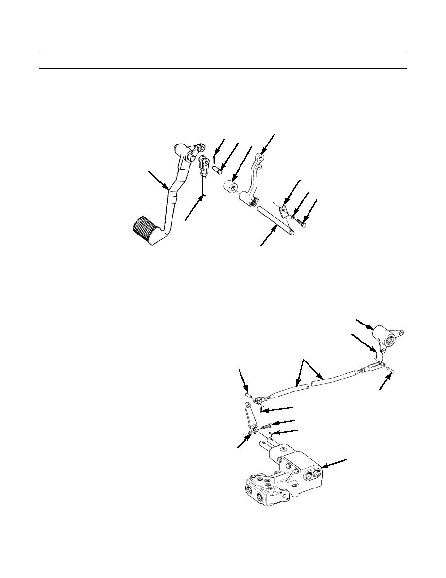
Raise brake foot pedal (33) as high as possible. Position lever (18) and spacer (35) between mounting bracket and other
clutch linkage lever.
18
30 31
35
33
29
28
27
32
34
387-399
4.
Insert shaft (34) through mounting bracket, lever (18), spacer (35) and other lever and mounting bracket.
5.
Install lock (29) with capscrew (27) and new lockwasher (28) to secure shaft (34).
6.
Install end of rod (32) on brake foot pedal (33) with pin (31) and new cotter pin (30).
7.
Install lever (25) on control valve (23) with new key
19
(26) and capscrew (24).
20
8.
Install one end of rod (22) on lever (25) with pin (21)
and new cotter pin (20).
22
9.
Repeat step 8 for other end of rod (22) at bellcrank
(19).
21
21
20
24
26
25
23
387-398
0148 00-6
|
|
Privacy Statement - Press Release - Copyright Information. - Contact Us |