 |
|||
|
|
|||
|
|
|||
| ||||||||||
|
|
 TM 5-2410-237-23
FINAL DRIVE BEARINGS ADJUSTMENT - CONTINUED
0128 00
ADJUSTMENT - CONTINUED
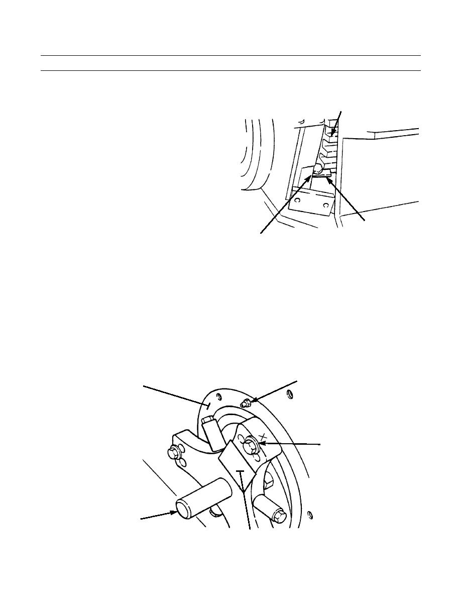
6.
Remove capscrew (8), nut (9) and lock (10) from
11
adjusting nut (11).
10
387-461
8,9
NOTE
All parts must be clean. Bearings must have lubricating oil on them. Adjusting nut must turn freely on
threads and bearing cage must move freely in holder.
7.
Install stand, bearing adjusting tool, washers and capscrews as follows:
a.
Install trunnion group (12) on track roller frame support assembly (13) using holes marked "Y". Trunnion arm
with identification "X" must be fastened to first hole with threads located to the right from grease fitting (14). See
instructions on decal (15).
14
13
Y
12
387-462
15
0128 00-2
|
|
Privacy Statement - Press Release - Copyright Information. - Contact Us |