 |
|||
|
|
|||
|
|
|||
| ||||||||||
|
|
 TM 5-2410-237-23
TORQUE CONVERTER OUTLET RELIEF VALVE REPLACEMENT - CONTINUED
0120 00
INSTALLATION - CONTINUED
8.
Perform power train hydraulic system tests (WP 0122 00). Perform Relief Valve Adjustment below as required.
9.
Run engine and test drive in all speeds.
10.
Install floor plates (WP 0171 00).
RELIEF VALVE ADJUSTMENT
NOTE
Adjustment can be performed without removing valve from torque divider.
1.
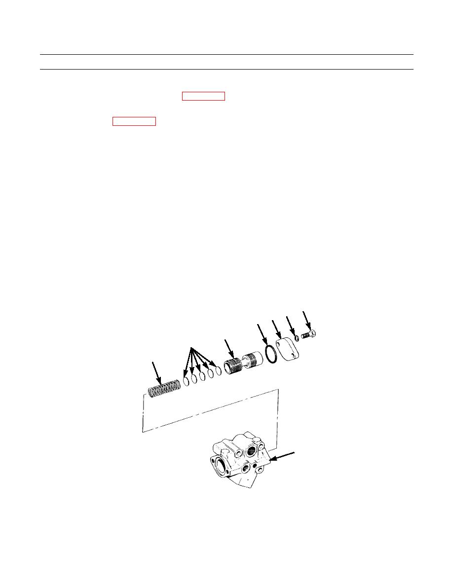
Remove two capscrews (13), lockwashers (14), cover (15) and O-ring (16) from relief valve (5). Discard O-ring and
lockwashers.
2.
Remove valve (17), five spacers (18) and spring (19).
3.
Add spacers (18) to increase relief valve setting. Remove spacers to decrease setting. Each 0.035 in. (90 mm) spacer will
change pressure by 2.9 psi (20 kPa).
4.
Install spring (19), required quantity of spacers (18) and valve (17).
NOTE
Lightly coat new O-ring with clean oil before installation.
5.
Position new O-ring (16) in relief valve (5) and install cover (15) with two new lockwashers (14) and capscrews (13).
Tighten capscrews to 18 lb-ft (24 Nm).
13
14
16 15
17
18
19
5
387-843
END OF WORK PACKAGE
0120 00-3
|
|
Privacy Statement - Press Release - Copyright Information. - Contact Us |
