 |
|||
|
|
|||
|
|
|||
| ||||||||||
|
|
 TM 5-2410-237-23
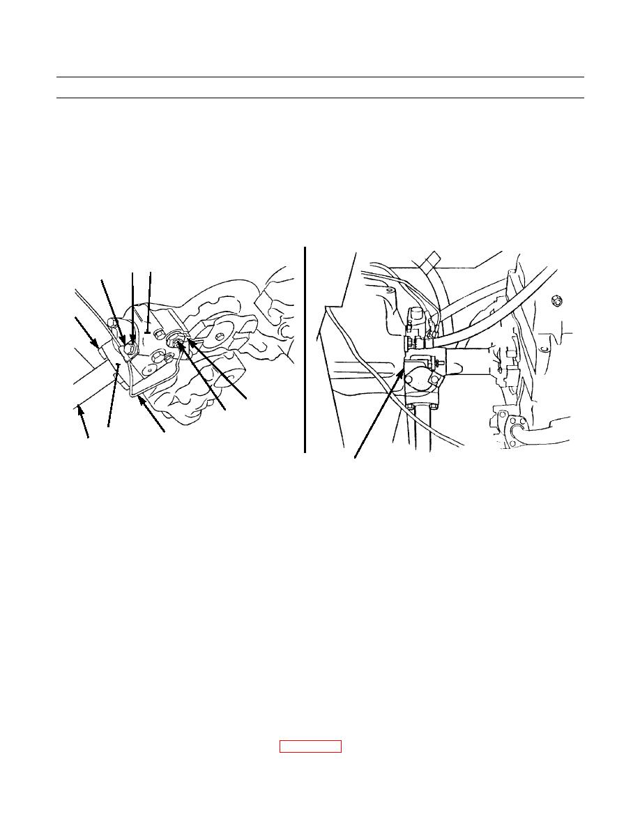
TORQUE CONVERTER OUTLET RELIEF VALVE REPLACEMENT - CONTINUED
0120 00
REMOVAL - CONTINUED
1.
Remove capscrew (1) and clip (2) from oil temperature sending unit line (3).
2.
Remove oil temperature sending unit (4) from relief valve (5).
3.
Remove four capscrews (6) and outlet tube (7) from relief valve (5). Remove O-ring (8) and discard.
4.
Remove three capscrews (9), lockwashers (10) and relief valve (5) from torque divider. Discard lockwashers.
5.
Remove two O-rings (11 and 12) from relief valve (5). Discard O-rings.
5
2
1
6
9,10
4
387-137
8 (HIDDEN)
3
7
11,12 (HIDDEN)
INSTALLATION
CAUTION
Care should be taken not to contaminate transmission oil system during installation of lines. Transmission
contamination can result in premature failure.
NOTE
Wipe area clean around torque divider, relief valve and all lines before installation.
Lightly coat new O-rings with clean oil before installation.
1.
Install two new O-rings (11 and 12) on relief valve (5).
2.
Position relief valve (5) on torque divider and install three new lockwashers (10) and capscrews (9).
3.
Install new O-ring (8) in outlet tube (7).
4.
Install outlet tube (7) to relief valve (5) with four capscrews (6).
5.
Install oil temperature sending unit (4) in relief valve (5).
6.
Secure oil temperature sending unit line (3) to relief valve (5) with clip (2) and capscrew (1).
7.
Check transmission oil level and add as needed (WP 0107 00).
0120 00-2
|
|
Privacy Statement - Press Release - Copyright Information. - Contact Us |
