 |
|||
|
|
|||
|
Page Title:
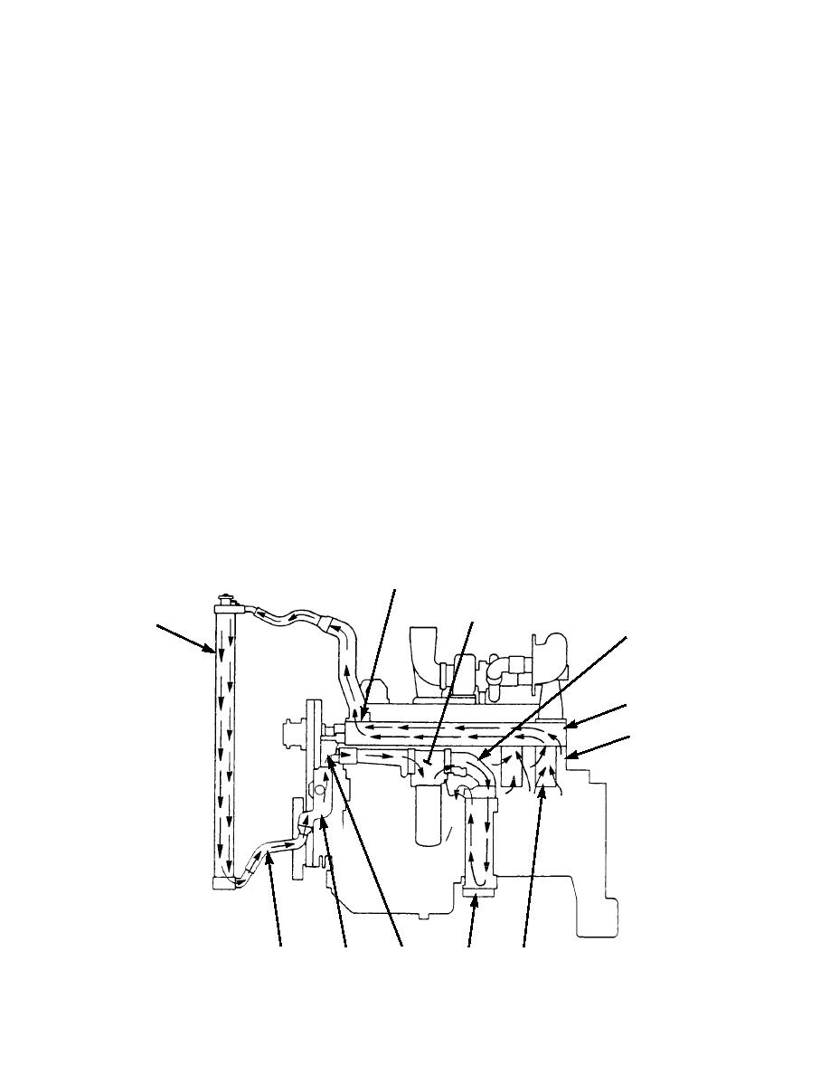
COOLING SYSTEM THEORY OF OPERATION |
|
||
| ||||||||||
|
|
 TM 5-2410-237-23
COOLING SYSTEM THEORY OF OPERATION
COOLING SYSTEM OPERATION
1.
The water pump (1) is on the left front side of the engine. It is gear-driven by the timing gears. Coolant from the bottom
of radiator (2) goes to water pump inlet (3). The rotation of the impeller in water pump (1) pushes coolant through the
system.
2.
The fluid filter head (4) sends the coolant flow through the transmission oil cooler (5) which is for the torque converter.
The flow goes through one side on the way into transmission oil cooler (5). At the bottom of transmission oil cooler (5)
the flow turns and goes back up through the other side and into the fluid filter head (4) again. The fluid filter head then
sends the coolant into cylinder block (6).
3.
Inside cylinder block (6) the coolant goes around cylinder liners (7) and up through the water directors into cylinder
head (8). The water directors send the flow of coolant around the valves and the passages for exhaust gases in cylinder
head (8). The coolant goes to the front of cylinder head (8). Here water temperature regulator (9) controls the direction
of the flow. If the coolant temperature is less than normal for engine operation, water temperature regulator (9) is closed.
The only way for the coolant to get out of cylinder head (8) is through internal bypass (10). The coolant from this line
goes into water pump (1) which pushes it through the cooling system again. The coolant from internal bypass (10) also
works to prevent cavitation (air bubbles) in the coolant. When the coolant gets to the correct temperature, water temper-
ature regulator (9) opens and coolant flow is divided. Most of the coolant goes through the radiator (2) for cooling. The
remainder goes through internal bypass (10) to water pump (1). The amount of the two flows is controlled by water tem-
perature regulator (9).
4.
Radiator (2) has a pressure relief cap and a filler cap. The pressure relief cap keeps the pressure in the cooling system
from getting too high when the engine is running. It also lets air come into the system when the pressure in the system is
less than atmospheric.
9
ENGINE
OIL COOLER
2
4
8
6
387-170
10
3
5
1
7
|
|
Privacy Statement - Press Release - Copyright Information. - Contact Us |
