 |
|||
|
|
|||
|
|
|||
| ||||||||||
|
|
 TM 5-2410-237-23
FUEL SYSTEM THEORY OF OPERATION - CONTINUED
0039 00
FUEL INJECTION NOZZLE - CONTINUED
3.
Fuel with high pressure from the fuel injection pump
19
15
14
goes into inlet passage (14). Fuel then goes through
filter screen (15) and into passage (16) to the area
below diameter (17) of valve (18). When the pressure
of the fuel that pushes against diameter (17) becomes
greater than the force of spring (19), valve (18) lifts
up. When valve (18) lifts, the tip of the valve comes
off of the nozzle seat and the fuel will go though the
387-172
nine 0.008 in. (0.203 mm) orifices (20) into the com-
20
18
17
16
bustion chamber.
4.
The injection of fuel continues until the pressure of
FUEL INJECTION NOZZLE
fuel against diameter (17) becomes less than the force
of spring (19). With less pressure against diameter
(17), spring (19) pushes valve (18) against the nozzle
seat and stops the flow of fuel to the combustion
chamber.
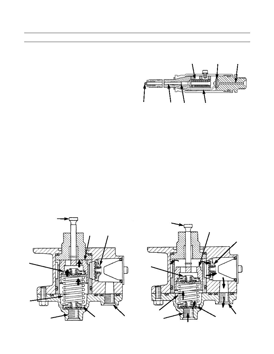
FUEL TRANSFER PUMP
1.
The fuel transfer pump is a piston pump that is moved by a cam (eccentric) on the fuel injection pump camshaft. The
transfer pump is located on the bottom side of the fuel injection pump housing.
2.
When the fuel injection pump camshaft turns, the cam moves push rod (21) and piston (22) down. As the piston moves
down, inlet check valve (23) and outlet check valve (24) close. Pumping check valve (25) opens and allows the fuel
below the piston to move into the area above the piston. Pumping spring (26) is compressed as the piston is pushed
down by push rod (21).
3.
As the fuel injection pump camshaft continues to turn, the cam no longer puts force on push rod (21). Pumping spring
(26) now moves piston (22) up. This causes pumping check valve (25) to close. Inlet check valve (23) and outlet check
valve (24) will open. As the piston moves up, the fuel in the area above the piston is pushed through the outlet check
valve (24) and out pump outlet port (27). Fuel also moves through pump inlet port (28) and inlet check valve (23) to fill
the area below piston (22). The pump is now ready to start a new cycle.
21
21
22
UPSTROKE
DOWN STROKE
22
24
(START)
(START)
24
25
25
26
FUEL TRANSFER
PUMP
26
27
27
28
28
23
23
0039 00-2
|
|
Privacy Statement - Press Release - Copyright Information. - Contact Us |
