 |
|||
|
|
|||
|
|
|||
| ||||||||||
|
|
 TM 5-2410-237-23
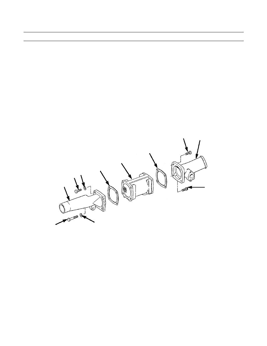
ENGINE OIL COOLER REPLACEMENT - CONTINUED
0020 00
REMOVAL - CONTINUED
6.
Remove three capscrews (11), capscrew (12), four washers (13), inlet water housing (5) and gasket (14) from oil cooler
(10). Discard gasket.
7.
Remove three capscrews (15), capscrew (16), outlet water flange (3) and gasket (17) from oil cooler (10). Discard gas-
ket.
INSTALLATION
1.
Position three capscrew (15) through outlet water flange (3) and install new gasket (17) on capscrews.
2.
Position outlet water flange (3) to oil cooler (10) and secure with three capscrews (15) and capscrew (16). Tighten cap-
screws to 32 lb-ft (45 Nm).
3.
Position three capscrews (11) and washers (13) through inlet water housing (5) and install new gasket (14) on cap-
screws.
4.
Position inlet water housing (5) to oil cooler (10) and secure with three capscrews (15), washer (13) and capscrew (12),
Tighten capscrews to 32 lb-ft (45 Nm).
15
3
17
10
14
13
11
5
16
13
12
387-844
5.
Slide three hoses (2) and six hose clamps (1) on outlet water flange (3), elbow flange (4) and inlet water housing (5). Do
NOT tighten clamps fully.
6.
Position two capscrews (6) through elbow flange (4) and install new gasket (9) on capscrews.
7.
Position oil cooler (10) and assembled components against cylinder block.
8.
Install two capscrews (6), capscrew (7) and washer (8).
9.
Tighten six hose clamps (1).
0020 00-2
|
|
Privacy Statement - Press Release - Copyright Information. - Contact Us |
