 |
|||
|
|
|||
|
|
|||
| ||||||||||
|
|
 6-27. Final Drive Pinion Group
a. Removal and Installation.
(1) Remove the steering clutch as outlined in
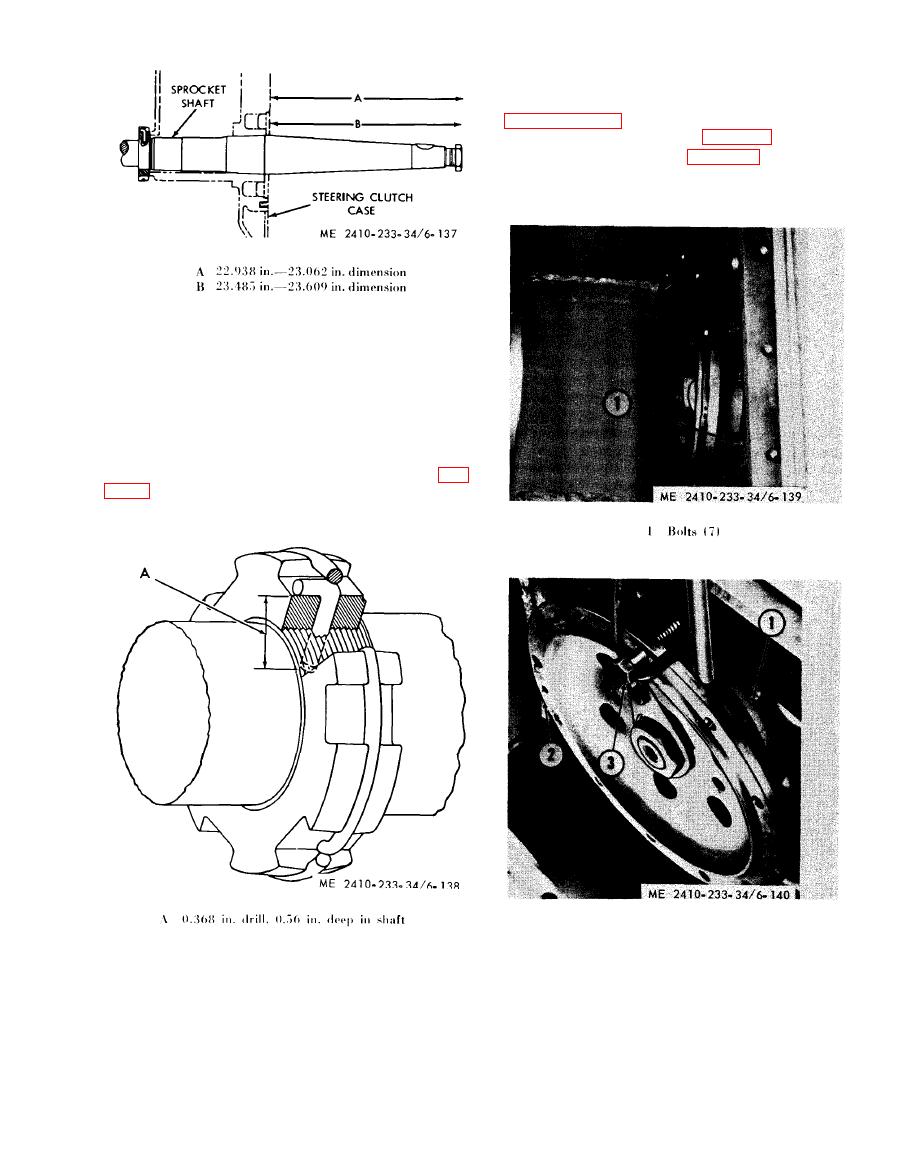
(2) Remove bolts (1, fig. 6-139).
(3) Insert a bolt (3, fig. 6-140) in one of the
steering clutch to pinion flange clearance holes and
attach a hoist for support.
installed.
(7) Maintaining the 55-60 tons pressure on
the shaft, tighten retaining nut with a spanner
wrench.
(8) When the retaining nut is securely
tightened, lock it in the following manner.
(9) n one of the notches in the retaining nut.
drill a 0. 368 inch diameter hole through the nut
and 0.56 inches deep into the sprocket shaft (A, fig.
lockring to hold it in place.
1 Cage
2 Flange
3 Bolt
d. Checking Sprocket Shaft. Check the final
drive sprocket shaft to determine if it is straight.
(4) Using a suitable pry bar, remove final drive
NOTE
pinion flange (2), bearing cage (1), inner bearing
If the sprocket shaft is bent more than the allowable
and final drive pinion as a unit from the steering
tolerance, shaft should be removed and a new shaft
clutch and bevel gear case.
installed.
|
|
Privacy Statement - Press Release - Copyright Information. - Contact Us |
