 |
|||
|
|
|||
|
|
|||
| ||||||||||
|
|
 (f) Place ring (6) and sleeve (5) over adapter
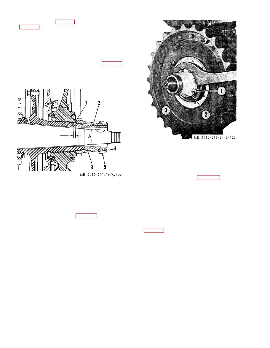
(3) and hub (3, fig. 6-122) and connect adapter (2,
(g) Place the pump control in the pulling
position and apply a slight press to the sprocket.
Rock the sprocket back and forth to equalize the
load.
(h) Press the sprocket on to 60-65 tons.
(i) When a new sprocket or final drive hub
has been installed, measure distance (A, fig. 6-122)
between the end of the sprocket and the end of the
splines on the final drive hub. Distance (A) should
be 0.44-0.56 inches.
1
Lock
2
Nut
3
Hub
(1) Remove the installation tools and install
the metal floating ring seals (para 6-22).
b. Sprocket Segments.
1 Lock
2 Nut
(1) General. The segmented sprockets consist
3 Hub
of a hub with sprocket segments bolted into place
4 Bearing cone
around the hub. Sprocket segments can be replaced
A Dimension to be checked
without removing the hub from the tractor.
(2) Removal.
(a) Remove dirt guards to provide access to
sprocket segments.
spanner wrench, install sprocket retaining nut (2).
(b) Loosen track adjustment and insert pin
(k) After locking the retaining nut, heat
(1, fig. 6-124) in the last slot of the segment (3) just
outer bearing cone (preferably in oil) and drive it
behind the segment (2) to be replaced.
onto final drive gear hub (3) until it seats against
retaining nut (2).
|
|
Privacy Statement - Press Release - Copyright Information. - Contact Us |