 |
|||
|
|
|||
|
Page Title:
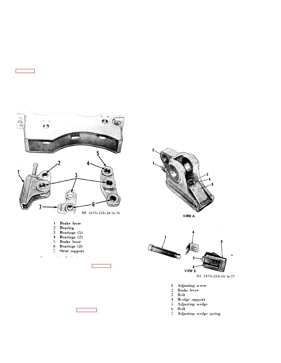
Figure 6-76. Brake lever bearings. |
|
||
| ||||||||||
|
|
 toward the needle bearing (7). Remove the key
(7) Remove bolts (7) securing shim pack (10)
(10).
and stop (11) to support assembly (3).
( 1 6 ) Pull the brake control lever (2), shaft (1)
(8) Remove the pins (14) that secure the brake
and key (13) as a unit and lift out the lever (6) and
toggle links (8 and 9) to the brake lever assemblies
washer (11). Inspect the needle bearings (7) and
(12), and remove the toggle links.
(12) for damage or excessive wear. Replace if
(9) Remove pins (15) securing brake struts
necessary.
( 1 6 ) to strut support assembly (13) and brake lever
(12).
NOTE
A suitable drift pin can be used for needle bearing
(10) Inspect bearings (2), (3), (4), and (6),
removal and installation, after removing the plug (9).
Drive in the new needle bearings from the stamped end
support (7). Replace bearings if they are worn or
to the dimensions show. Fill the needle bearing
damaged.
compartments with an approved ball GAA grease.
Stake the plug (9) in three places to secure it to the
NOTE
steering clutch cover at assembly.
An arbor press can be used for all bearing removal and
of
installation.
(17) Reassemble in reverse order
disassembly.
NOTE
Refer to subparagraph e below for adjustment of
brake engaging mechanism prior to installation in the
steering clutch and bevel gear case.
(11) Place adjusting screw (1, fig. 6-77) in as
low a position as is necessary to remove wedge
support (4) and brake adjustment wedge (5).
(12) Remove adjusting screw (1), bolt (3),
w h i c h secures wedge support (4) to brake lever (2),
and adjusting wedge (5).
(13) Remove bolt (6) and adjusting screw
spring (7) from adjusting wedge.
(14) Remove bolt (5, fig. 6-78) securing the
brake lever (6) to the brake shaft (1) in steering
clutch cover (8).
(15) Slide the lever (6) along the shaft (1)
|
|
Privacy Statement - Press Release - Copyright Information. - Contact Us |
