 |
|||
|
|
|||
|
|
|||
| ||||||||||
|
|
 b. Removal and Installation.
(1) Remove the fuel tank (para 5-14).
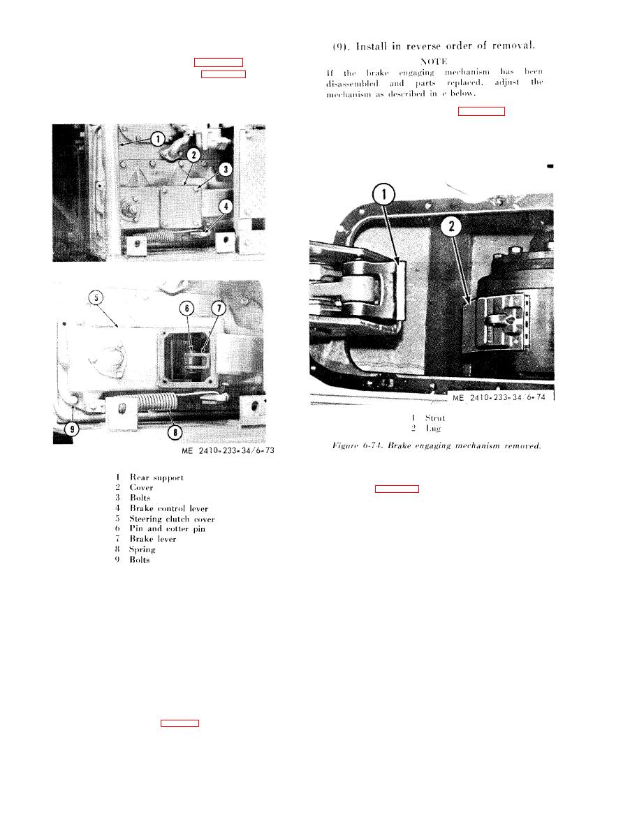
(2) Remove rear support (1, fig. 6-73)
(3) Remove bolts (3) and cover (2).
(4) Disconnect the brake rod attached to the
brake control lever (4).
(10) Tighten bolts (9, fig. 6-73) securing
s t e e r i n g clutch cover (5) to the bevel gear case, to
100 5 lb-ft.
c. Disassembly and Reassembly.
( 1 ) R e m o v e t h e a d j u s t i n g screw
socket
assembly (2, fig. 6-75).
( 2 ) Remove brake lever shaft (1) which joins
the brake lever (17) and the brake strut support
assembly (13) and secures them to the brake
linkage support assembly (3).
(3) Remove brake lever shaft (4).
( 4 ) Remove the retaining ring and pull the pin
( 6 ) securing the brake toggle links (8) and (9) to
the brake link (5).
(5) Remove the pin and cotter pin (6) securing
(5) Remove brake toggle link (9) and front
the brake link to the brake lever (7).
brake lever assembly (12) as a unit.
(6) Remove brake lever return spring (8).
(6) Guide the links (8) between the two
( 7 ) Remove bolts (9) and steering clutch cover
support assembly braces, and lift off the support
(5).
assembly (3).
( 8 ) Remove the bolts securing brake engaging
mechanism to the bevel gear case, and lift the
e n g a g i n g mechanism to the bevel gear case, and lift
the engaging mechanism straight up.
NOTE
The brake band struts (1, fig. 6-74) will disengage
from the brake band. Be sure the struts engage the lugs
(2) on the brake band at the time of installation.
|
|
Privacy Statement - Press Release - Copyright Information. - Contact Us |