 |
|||
|
|
|||
|
Page Title:
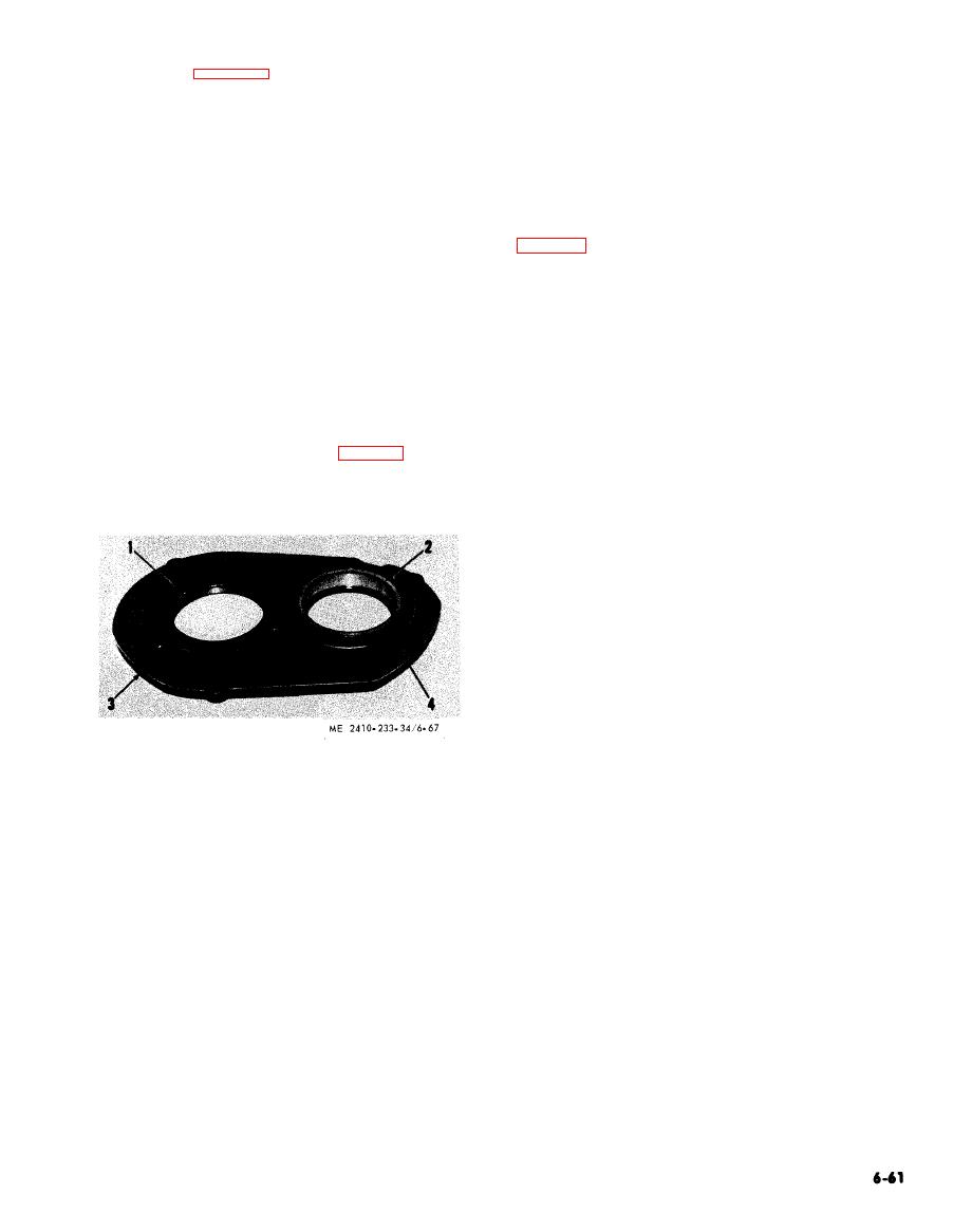
Figure 6-67. Bearing outer race removal. |
|
||
| ||||||||||
|
|
 6-10 Transmission Lubrication Junction Block
Key to figure 6-66.
1 Plate
a. General. The transmission lubrication junction
2 Bolts
block, located on the front of the transmission case,
3 Lock
directs the flow of the transmission lubricating oil.
4 Bearing inner race and roller assembly
b. Removal and Installation.
5 Gear
6 Spacer
(1) Remove the floor plates.
7 Bearing inner race and roller assembly
(2) Refer to TM 5-2410-233-20 and drain the
8 Bevel pinion
transmission lubrication system.
(3) Disconnect the junction block outlet line
Place the cover on blocks and also place a
(6)
block under the bevel pinion shaft to prevent
CAUTION
dam age to the teeth on the-shaft when it is re-moved.
C o v e r all openings to prevent the entry
(7) Drive out bevel pinion (8).
( 8 ) Inspect bearing inner race and roller
o f dirt or other foreign matter into the
assembly (4).
hydraulic system.
(9) Remove gear (5) and spacer (6).
(4) Remove the junction block.
( 1 0 ) Inspect bearing inner race and roller
(5) Replace all damaged or worn parts.
a s s e m b l y (7) on the bevel pinion shaft. If the
(6) Install in the reverse order of removal.
bearing needs to be replaced, it can be removed
with a push puller and a bearing cup pulling a t -
tachment.
(11) Remove plugs (3, 4, fig. 6-67) and the
dowels beneath the plugs, then remove the bearing
outer races (1) and (2).
1
Transfer gear bearing outer race
2
Bevel pinion shaft bearing outer race
3
Plug
4
Plug
|
|
Privacy Statement - Press Release - Copyright Information. - Contact Us |