 |
|||
|
|
|||
|
Page Title:
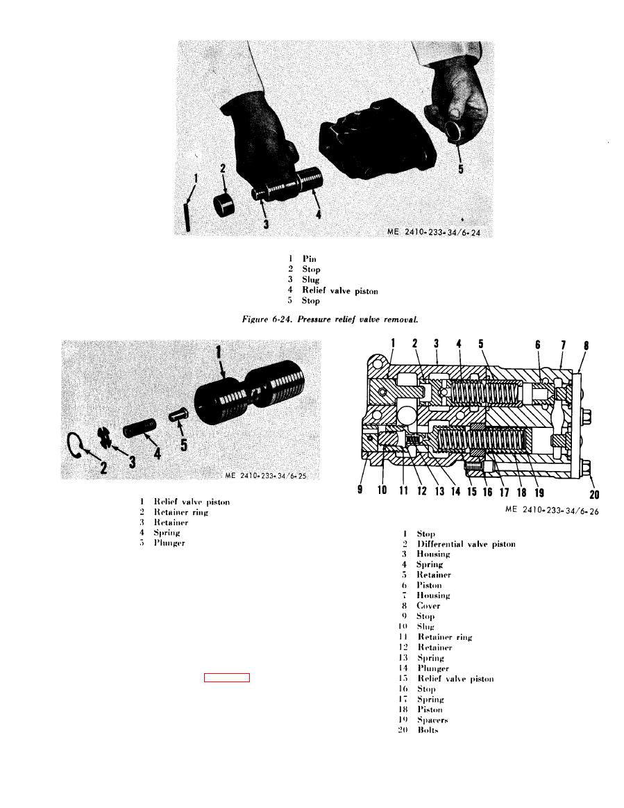
Figure 6-25. Pressure relief valve disassembly. |
|
||
| ||||||||||
|
|
 (2) Pressure control value inspection and
repair. Inspect valve housings and pistons for
nicks, burrs, or pitting. Inspect the valve body land
e d g e s for wear caused by recirculating of abrasive
particles. Light scratches and light grey wear
a p p e a r a n c e are not detrimental to valve. Replace
all springs when reconditioning a valve with ap-
preciable service hours. Valves must move freely in
housings. Be sure slug (10, fig. 6-26), is free to
move in relief valve piston (15). Inspect pistons (6)
a n d (15) to make certain orifices are open. Check
drain hole in stop (9) to be sure it is open. Install
new preformed packings when assembling control
valve.
|
|
Privacy Statement - Press Release - Copyright Information. - Contact Us |