 |
|||
|
|
|||
|
|
|||
| ||||||||||
|
|
 in. - 10NC
forged
c a u s e the valve head to break off during
(12)
Install
two
service.
eyebolts and attach a hoist to the cylinder head (19)
a n d remove from the tractor. Discard the cylinder
d. Reassembly and Installation (fig. 5-40).
head gasket (20).
(1) Install the seals (30 and 31) onto the
precombustion chambers (29).
( 1 3 ) Using a spring compressor, compress the
springs (23). Remove the retainers (21). Release
( 2 ) Coat the chamfered portion of the cylinder
head and the rubber seals (30) with liquid soap.
the spring compressor and remove the retainers
I n s t a l l the precombustion chambers in the cylinder
(22), springs (23) and guides (24).
h e a d and tighten to a torque of 140 to 160 foot-
( 1 4 ) Remove the valves (25) and valve seats
pounds.
(26). Remove the locating dowels (27).
(15) Using a wire about 15 inches long with a
(3) Install the dowels (27) in the block. Install
a new gasket (20). Install the plug (32).
hook at one end, remove the valve lifters (28) from
( 4 ) Install the valve lifters (28).
the block.
(5) Press the valve guides (24) into the
(16)
Remove
the
precombustion
chambers
c y l i n d e r head using an arbor. Resurface the valve
(29) and seals (30 and 31).
seats after installing in the cylinder head. Lap
( 1 7 ) Remove the plug (32) from the cylinder
valves and seats together to obtain a proper seal.
bead.
(6) Shrink the valve seats (20) in dry ice and
b. Cleaning. Remove all traces of carbon and
install in the head. Drive into place with a suitable
o t h e r deposits with a clean cloth dampened with
driver.
c l e a n i n g solvent (Fed. Spec. P-D-680). Blow out oil
(7) Lubricate the
valves
(25)
with
clean
a n d coolant passages with compressed air.
engine oil and install.
c. Inspection and Repair.
(8) Install the valve springs (23) and retainers
(1) Inspect the rocker arm shaft for scoring or
(22). Compress the springs and install the retainers
wear. If the shaft has been damaged by rocker arm
(21).
m o v e m e n t , replace the shaft.
(9) Coat the push rods (16) with clean engine
( 2 ) Check rocker arm bushings for scratches,
o i l and install in the block.
pitting or scoring. Replace the bushings if
damaged.
( 1 0 ) Install the cylinder head (19) and secure
( 3 ) Place each rocker arm in position on the
with the washers (18) and bolts (17). Coat the
shaft. The rocker arm must rest freely on the shaft
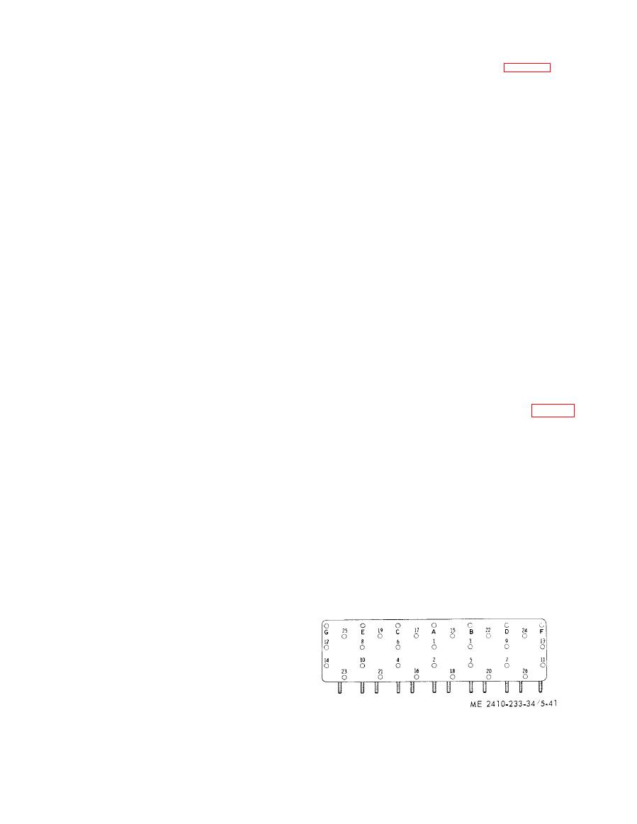
threads of the bolts with a sealant. Refer to figure 5-
w i t h o u t side wobble. If wobble exists, replace the
41 and tighten as follows:
rocker arm.
(a) Step 1. T i g h t e n b o l t s i n n u m e r i c a l
springs for cracks and
(4) Inspect the
order to 115 foot-pounds.
w e a k n e s s . Replace springs as necessary.
( b ) Step 2. R e t i g h t e n b o l t s i n n u m e r i c a l
(5) Inspect the cylinder head for fretting,
order to 170 to 180 foot-pounds.
erosion and warping in excess of 0.005 inch.
(c) S t e p 3 . R e t i g h t e n b o l t s i n n u m e r i c a l
R e s u r f a c e the bead if necessary.
order
(band
torque
only)
to
170
to
180
foot-
(6) Inspect the push rods for straightness,
pounds.
cracks and worn ends. Replace if bent.
( d ) Step 4 . T i g h t e n b o l t s i n a l p h a b e t i c a l
(7) Using a micrometer, measure the valve
order to 22 foot-pounds.
guide
inner diameter. The diameter should be
(e) S t e p 5. Retighten bolts in alphabetical
0 . 3 7 3 6 to 0.3756 inch and must not exceed 0.3766
order to 27 to 37 foot-pounds.
i n c h . Replace if wear is excessive.
(f) Step 6. R e t i g h t e n b o l t s i n a l p h a b e t i c a l
( 8 ) Inspect and repair the valves as follows:
order (hand torque only) to 27 to 37 foot-pounds.
(a) I n s p e c t t h e v a l v e s f o r d a m a g e . I f t h e
valve faces are pitted or do not properly contact the
valve seats, reface the valves. Ensure that there is
e n o u g h metal on the head of tbe valve to prevent
d i s h i n g . Replace the valves if they are excessively
damaged
or
worn.
s t e m diameter at three places. Diameter must not
be less than 0.3702 inch at any point.
CAUTION
While handling valves, be careful not to
scratch or nick the area between the
valve face and stem. A small nick can
|
|
Privacy Statement - Press Release - Copyright Information. - Contact Us |
