 |
|||
|
|
|||
|
Page Title:
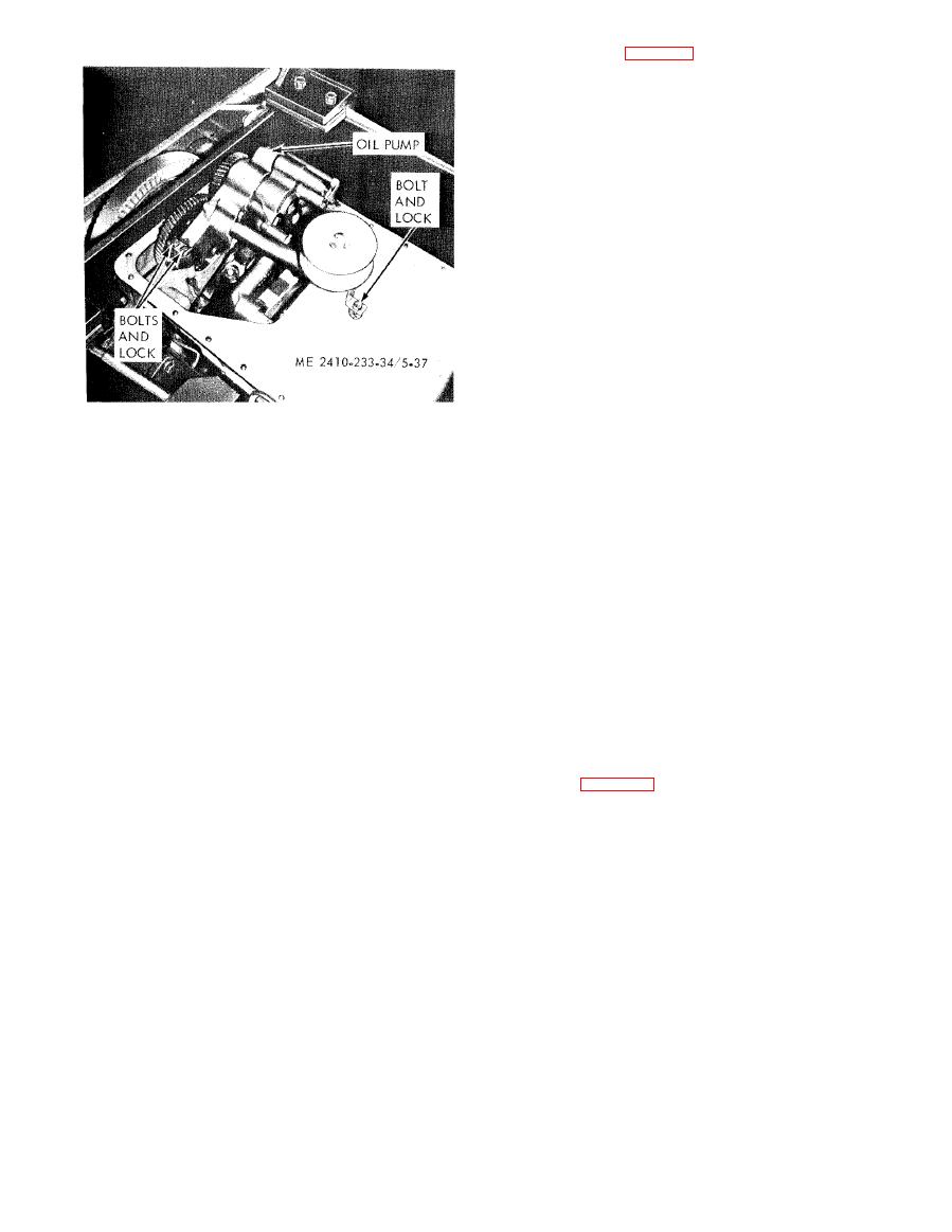
Figure 5-37. Oil pump, removal and installation. |
|
||
| ||||||||||
|
|
 b. Disassembly (fig. 5-38).
(1) Remove the bolts (1), lock (2) and cover
(3). Remove the spring (4) and plunger (5).
( 2 ) Remove the bolts (6), lock (7), elbow (8)
and gasket (9).
(3) Remove the bolts (10, 11 and 12) and
l o c k s (13, 14, and 15). Remove the scavenge pump
body (16) from the oil pump body and press out the
bearings (17) and pins (18).
Key to figure 5-38.
22
Gasket
23
Gear
1
Bolt
24
Key
2
Lock
25
Gear
3
Cover
26
Spacer
4
Spring
27
Cotter pin
5
Plunger
28
Nut
6
Bolt
29
Washer
7
Lock
30
Gear
8
Elbow
31
Key
9
Gasket
32
Shaft and
10
Bolt
gear assembly
11
Bolt
33
Bearing
12
Bolt
34
Gear
13
Lock
35
Shaft
14
Lock
36
Dowel
15
Lock
37
Shaft and
16
Body
gear assembly
17
Bearing
38
Bearing
18
Pin
39
Bearing
19
Bolt
40
Ball
20
Lock
41
Body
21
Suction bell
|
|
Privacy Statement - Press Release - Copyright Information. - Contact Us |
