 |
|||
|
|
|||
|
Page Title:
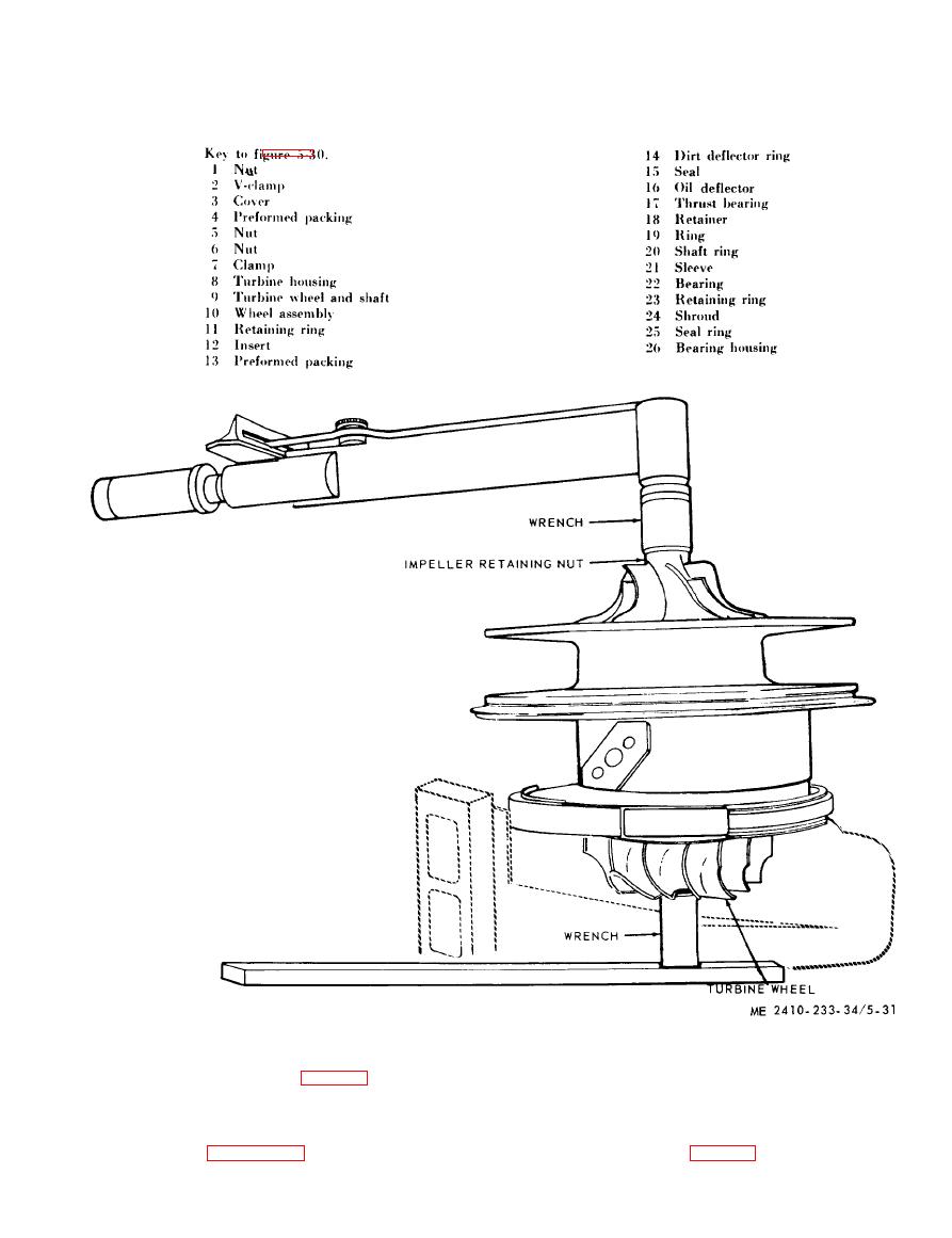
Figure 5-31. Turbocharger retaining nut, removal and installation. |
|
||
| ||||||||||
|
|
 (5) Remove nut (6) (fig. 5-30), expand clamp
wheel will clear base of press during removal. Place
(7) and lift the center section out of the turbine
a pin or dowel on end of shaft, hold the turbine
housing (8).
wheel by hand, press against the pin until shaft is
(6) Place the unit in an arbor press as
free and remove the turbine wheel shaft (9) and
illustrated in figure 5-32. Make sure the turbine
wheel assembly (10, fig. 5-30).
|
|
Privacy Statement - Press Release - Copyright Information. - Contact Us |