 |
|||
|
|
|||
|
Page Title:
Chapter 5. REPAIR OF THE POWER PLANT |
|
||
| ||||||||||
|
|
 R E P A I R OF THE POWER PLANT
Section I. COOLING SYSTEM
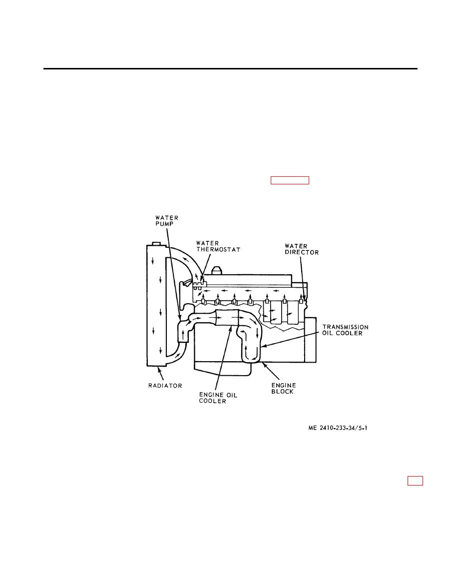
5-1. General
coolant becomes sufficiently warm, the regulator
opens to permit the coolant to return to the
Cooling system components are the radiator, water
radiator. The coolant is cooled by air forced
pump, water temperature regulator, oil cooler and
through the radiator core. The cooling system is
lines, fittings and passages. Coolant pumped from
pressurized to permit safe operation at tem-
the outlet side of the water pump flows directly into
peratures higher than the normal boiling point,
the front of the cylinder block and to the oil cooler.
prevent cavitation in the water pump and reduce
The coolant passes through the oil cooler, returns to
the possibility of air pockets in the coolant passages.
the block, and flows around the cylinder liner walls
Refer to figure 5-1 for the cooling system schematic
to the precombustion chambers. The coolant then
diagram.
flows to the water temperature regulator. When the
233-10) and remove engine upper right guard
5-2. Radiator
assembly (TM 5-2410-233-20).
a. Removal.
(2) Remove the hood, headlight brackets (fig.
(1) Drain the cooling system (TM 5-2410-
5-2) and radiator top guard.
|
|
Privacy Statement - Press Release - Copyright Information. - Contact Us |
