 |
|||
|
|
|||
|
|
|||
| ||||||||||
|
|
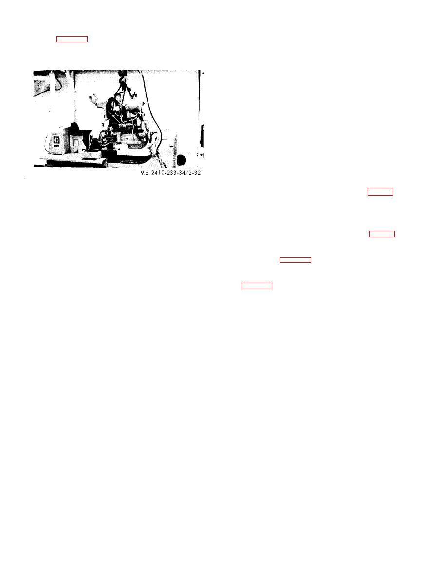 (25) Attach a suitable hoist and remove the
(3) If universal joint wobbles perceptibly,
engine (fig. 2-32).
c l o s e r alignment is needed.
d. Misalignment.
NOTE
(1) Normally misalignment can be corrected
Engine weighs 2700 lbs.
by adding or removing shims as necessary between
t h e frame and the engine supports.
(2) If it is necessary to shift the engine from
one side to the other in the frame, loosen the
h o l d d o w n bolts and shift the engine accordingly.
(3) If the holes for the holddown bolts are
enlarged, dowels should be installed to hold the
engine in the proper location after it is bolted down.
(4) Extreme misalignment is probably the
r e s u l t of bent main frame channels, in which case
they should be replaced, Extreme wear in the
e n g i n e front support will also cause misalignment.
Transmission
e. Removal.
(1) Remove the brake pedal assembly (para 6-
30).
b. Installation. R e v e r s e r e m o v a l p r o c e d u r e a n d
(2) Drain oil from transmission (LO 5-2410-
i n s t a l l the engine. Fill cooling system (TM 5-2410-
233-12).
233-20). Fill transmission with oil to specified level
(3) Disconnect wiring from the disconnect
(LO 5-2410-233-12).
switch mounted on the seat frame assembly (fig. 2-
c. Engine Alignment.
33, sheet 1).
(1) Place the quantity of shims required
between the engine supports and the tractor frame
(4) Disconnect the transmission hydraulic
control linkage (fig. 6-71) from the seal frame
i n order to align the universal joint as closely as
assembly.
possible.
(2) After installation of the engine and
(5) Remove the seat frame assembly mounting
bolts (fig. 2-33, sheet 1), Attach a hoist and remove
u n i v e r s a l joint is complete, a visual check of the
seat frame assembly.
alignment can be made while rotating the universal
joint.
|
|
Privacy Statement - Press Release - Copyright Information. - Contact Us |
