 |
|||
|
|
|||
|
Page Title:
Figure 2-26. Compressing seals. |
|
||
| ||||||||||
|
|
 CAUTION
4. Place a seal on the expander. Turn the
Under
no
circumstances
should
c r a n k on the expander until the inside face of the
welding
be done on the wall of the
movable block is slightly past point (A). Then
cylinder except the welded area at the
return to point (A). Rotate the seal 90 on the
head end of the cylinder. Welding on
expander and expand again. Check to see if the seal
the cylinder wall can cause enough bore
will slip off the expander. If not, repeat the
distortion to cause interference between
procedure, expanding the seal farther each time,
t h e piston and the cylinder wall and can
until the seal will slip off the expander when block
result in severe scoring of the cylinder
i s returned to point (A).
wall.
5. Lubricate the outer seals and place
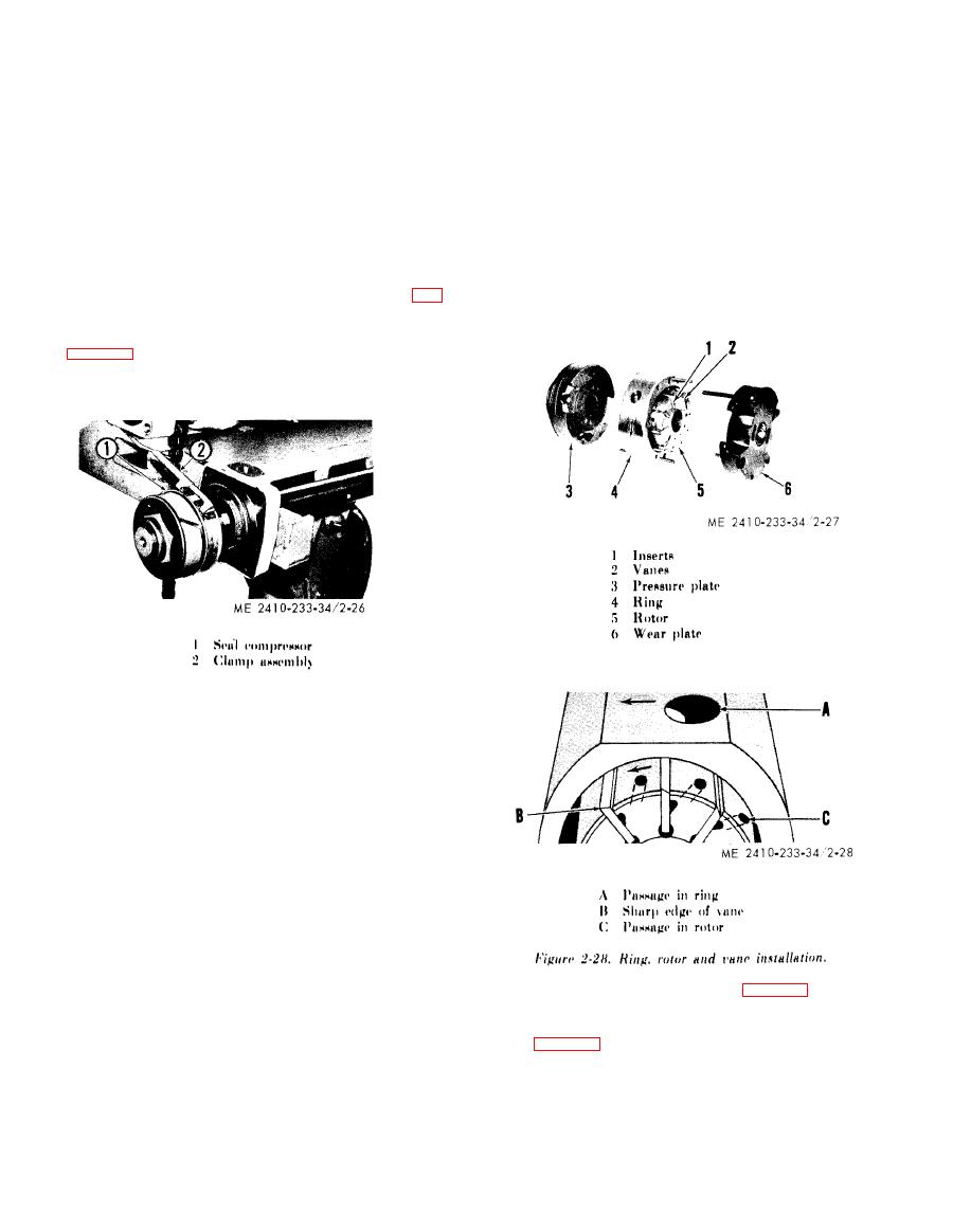
(10) Vane type pumps.
t h e m on the piston. Install and lubricate the wear
(a) Before disassembling a pump, mark the
ring.
pump body and cover to insure correct assembly
6. Select the applicable compressor (1, fig.
w i t h respect to port relationship.
2 - 2 6 ) and install the clamp (2) on the compressor.
P l a c e the compressor loosely over the outer seals
( f i g . 2-26). Place the compressor on the piston so
the rolled side of the compressor will be facing the
cylinder when the piston is installed in the cylinder.
Figure 2-26. Compressing seals.
7. Slowly turn the handle on the clamp
and force the seals into their grooves. Be certain the
seals are being settted in their grooves as they are
being compressed.
8. P l a c e t h e p i s t o n a s s e m b l y i n t o t h e
cylinder bore as illustrated; be certain the piston is
s q u a r e in the bore.
9. Drive on the piston rod until the entire
piston assembly is in the cylinder bore. Remove the
clamp and the compressor.
10. Install the bolts securing the cylinder
h e a d to the cylinder with the piston rod fully ex-
tended. Tighten the bolts to the torque value in the
SPECIFICATIONS.
(9) C y l i n d e r i n s t a l l a t i o n . B e f o r e i n s t a l l i n g a
hydraulic cylinder, apply FED SPEC TT-A-580
inserts (1)) in the rotor (5) and the rotor into the
A n t i - S e i z e Compound to the cylinder pins and pin
ring (4). The sharp edges of the vanes (2) and the
b o r e s to aid in future removal. After the cylinder
arrows (fig. 2-28) on the ring and rotor must point
has been installed, start the engine and operate the
in the direction of PUMP ROTATION when the
c y l i n d e r to remove air from the hydraulic system.
cartridge is installed in the pump cover. Note that
When the system is functioning properly, check the
the passage (A) and passages (C) are angled toward
level of the oil in the hydraulic oil supply tank.
t h e direction of pump rotation.
|
|
Privacy Statement - Press Release - Copyright Information. - Contact Us |
