 |
|||
|
|
|||
|
|
|||
| ||||||||||
|
|
 TM 5-2410-233-23
BLADE AND PUSHARM ASSEMBLY REPLACEMENT - CONTINUED
0170 00
INSTALLATION - CONTINUED
WARNING
Do NOT remove hydraulic tank filler cap or disconnect or remove any hydraulic system line
or fitting unless hydraulic system pressure has been relieved. Hydraulic system pressure can
be over 2500 psi (17,237 kPa), even with engine and pump OFF. To relieve pressure, lower all
hydraulic attachments to the ground and shut down engine. Move control levers through all
operating positions, then SLOWLY loosen hydraulic tank filler cap. After maintenance,
tighten all connections before applying pressure. Escaping hydraulic oil under pressure can
penetrate the skin, causing serious injury or death.
At operating temperature hydraulic oil is hot. Allow hydraulic oil to cool before disconnecting
any hydraulics. Failure to do so could result in injury. Insert pipe nipple, located in tractor
toolbox, into hydraulic tank drain valve.
5.
Relieve hydraulic system pressure (WP 0176 00).
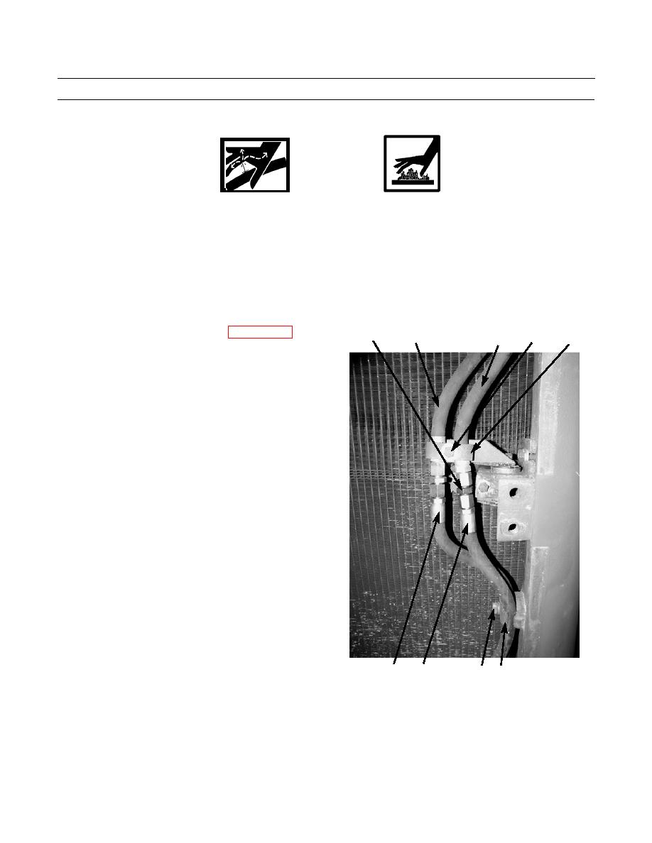
14
9
5,6,7
8
10
6.
Disassemble hose (13), nipple (14) and hose (12).
7.
Disassemble hose (10), nipple (15) and hose (9).
8.
Assemble hose (9), nipple (15) and hose (12).
9.
Assemble hose (10), nipple (14) and hose (13).
10.
Secure tilt cylinder hoses (12 and 13) to radiator guard
with clamp (11), new lockwasher (7) and bolt (6).
11.
Secure tilt cylinder hoses (9 and 10) to radiator guard
with clamp (8), bolt (6), new lockwasher (7) and nut
(5).
386-527
13
12
6,7 11
0170 00-4
|
|
Privacy Statement - Press Release - Copyright Information. - Contact Us |
