 |
|||
|
|
|||
|
Page Title:
PRESSURE RELIEF VALVE TESTS - CONTINUED |
|
||
| ||||||||||
|
|
 TM 5-2410-233-23
HYDRAULIC SYSTEM TESTS - CONTINUED
0167 00
PRESSURE RELIEF VALVE TESTS - CONTINUED
c.
If equipped with a ripper, run engine at low idle and raise ripper until lift cylinders bottom out. Main relief valve
should open 2250 + 50 or 0 psi (158.2 + 3.5 or 0.0 kg/cm2).
d.
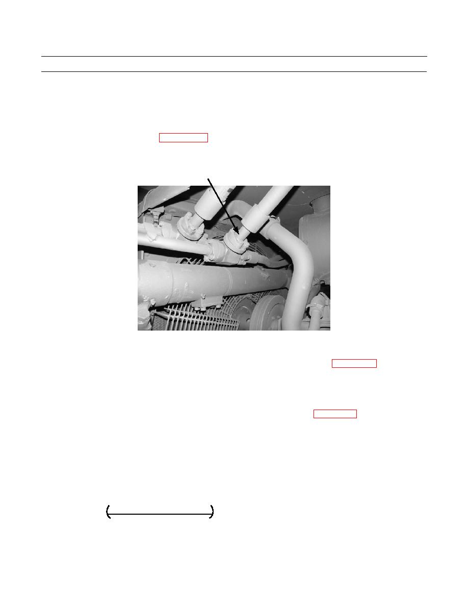
If equipped with a winch, block line to head end of blade lift cylinders, located on left side of engine compartment
above lift cylinder mounting tube.
(1)
Disconnect hose (5) (WP 0160 00).
(2)
Install O-ring and cover and reconnect hose (5).
5
386-825
e.
With engine at low idle, operate blade control lever to extend lift cylinders. Main relief valve should open at 2250
+ 50 or 0 psi (158.2 + 3.5 or 0.0 kg/cm2).
f.
Return blade to lowered position. Remove cover and O-ring and reconnect hose (5) (WP 0160 00).
NOTE
One shim (part number 3J743) changes pressure by 35 psi (241 kPa).
g.
To adjust main relief valve setting, perform Relief Valve Setting Adjustment in WP 0151 00.
PUMP EFFICIENCY TEST (ON MACHINE)
1.
Install flow meter.
2.
Start engine and run at 2000 RPM.
Measure pump flow at 100 psi (7.0 kg/cm2) with engine at 2000 RPM.
3.
Measure pump flow at 1000 psi (70.3 kg/cm2) with engine at 2000 RPM.
4.
5.
Calculate percentage of flow loss using the following formula:
gpm @ 100 psi - gpm @ 1000 psi x 100 =
Percentage of flow loss
gpm @ 100 psi
6.
If percentage of flow loss is more than 10%, pump performance is not sufficient.
0167 00-8
|
|
Privacy Statement - Press Release - Copyright Information. - Contact Us |
