 |
|||
|
|
|||
|
Page Title:
PRESSURE RELIEF VALVE TESTS |
|
||
| ||||||||||
|
|
 TM 5-2410-233-23
HYDRAULIC SYSTEM TESTS - CONTINUED
0167 00
PRESSURE RELIEF VALVE TESTS
WARNING
Do NOT remove hydraulic tank filler cap or disconnect or remove any hydraulic system line
or fitting unless hydraulic system pressure has been relieved. Hydraulic system pressure can
be over 2500 psi (17,237 kPa), even with engine and pump OFF. To relieve pressure, lower all
hydraulic attachments to the ground and shut down engine. Move control levers through all
operating positions, then SLOWLY loosen hydraulic tank filler cap. After maintenance,
tighten all connections before applying pressure. Escaping hydraulic fluid under pressure can
penetrate the skin, causing serious injury or death.
At operating temperature hydraulic oil is hot. Allow hydraulic oil to cool before disconnecting
any hydraulics. Failure to do so could result in injury.
1.
Tilt Relief Valve.
a.
Operate machine until hydraulic system is at operating temperature. Lower implements to the ground, so that bull-
dozer blade is level. Shut down engine. Move all hydraulic control levers to all positions to relieve pressure in
lines. Return all control levers to HOLD position.
b.
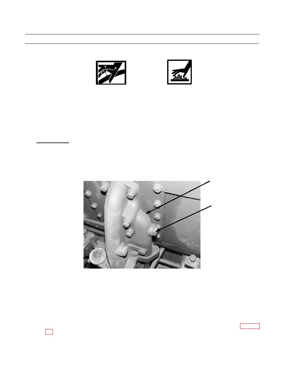
Install a 0-4000 psi (0-281.2 kg/cm2) gage in pressure tap (1) located on tilt valve inlet manifold (2).
2
1
386-668
c.
Raise blade high enough to allow for maximum tilt in either direction.
d.
With engine at low idle, extend or retract tilt cylinder to full extent of travel. Observe gage reading. Maximum
gage reading should be 2450 psi 25 psi (16892 kPa 172 kPa).
e.
Return blade to level position and lower to the ground.
NOTE
One shim (part number 3J747) changes pressure by 35 psi (241 kPa).
f.
To adjust tilt relief valve setting, remove tilt control valve and perform Relief Valve Setting Adjustment (WP 0150
0167 00-6
|
|
Privacy Statement - Press Release - Copyright Information. - Contact Us |
