 |
|||
|
|
|||
|
|
|||
| ||||||||||
|
|
 TM 5-2410-233-23
BLADE CONTROL LEVER AND LINKAGES REPLACEMENT - CONTINUED
0152 00
ADJUSTMENT - CONTINUED
2.
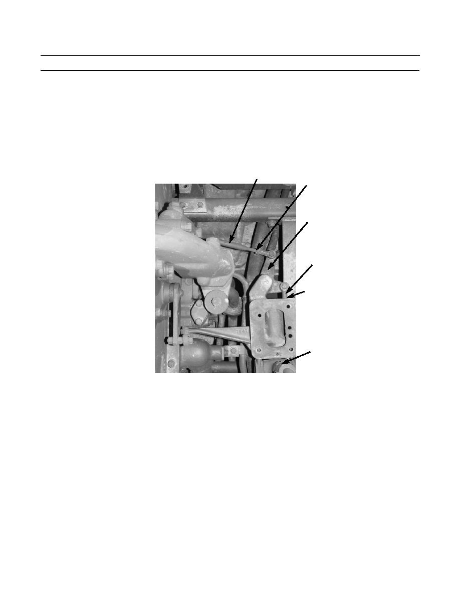
Adjust blade control linkages:
a.
Loosen two jam nuts (20) on linkage rod (16) between bell crank (14) and main (bulldozer) control valve lever
located under hydraulic tank.
b.
Loosen two jam nuts (21) on linkage rod (11) between bell crank (14) and blade control lever (12).
c.
Turn linkage rods (16 and 11) until blade control lever (12) and main (bulldozer) control valve lever are in center
of travel position.
d.
Tighten jam nuts (20 and 21) while holding linkage rods (16 and 11).
16
20
14
11
21
(HIDDEN)
12
386-771
END OF WORK PACKAGE
0152 00-5
|
|
Privacy Statement - Press Release - Copyright Information. - Contact Us |
