 |
|||
|
|
|||
|
Page Title:
RELIEF VALVE SETTING ADJUSTMENT |
|
||
| ||||||||||
|
|
 TM 5-2410-233-23
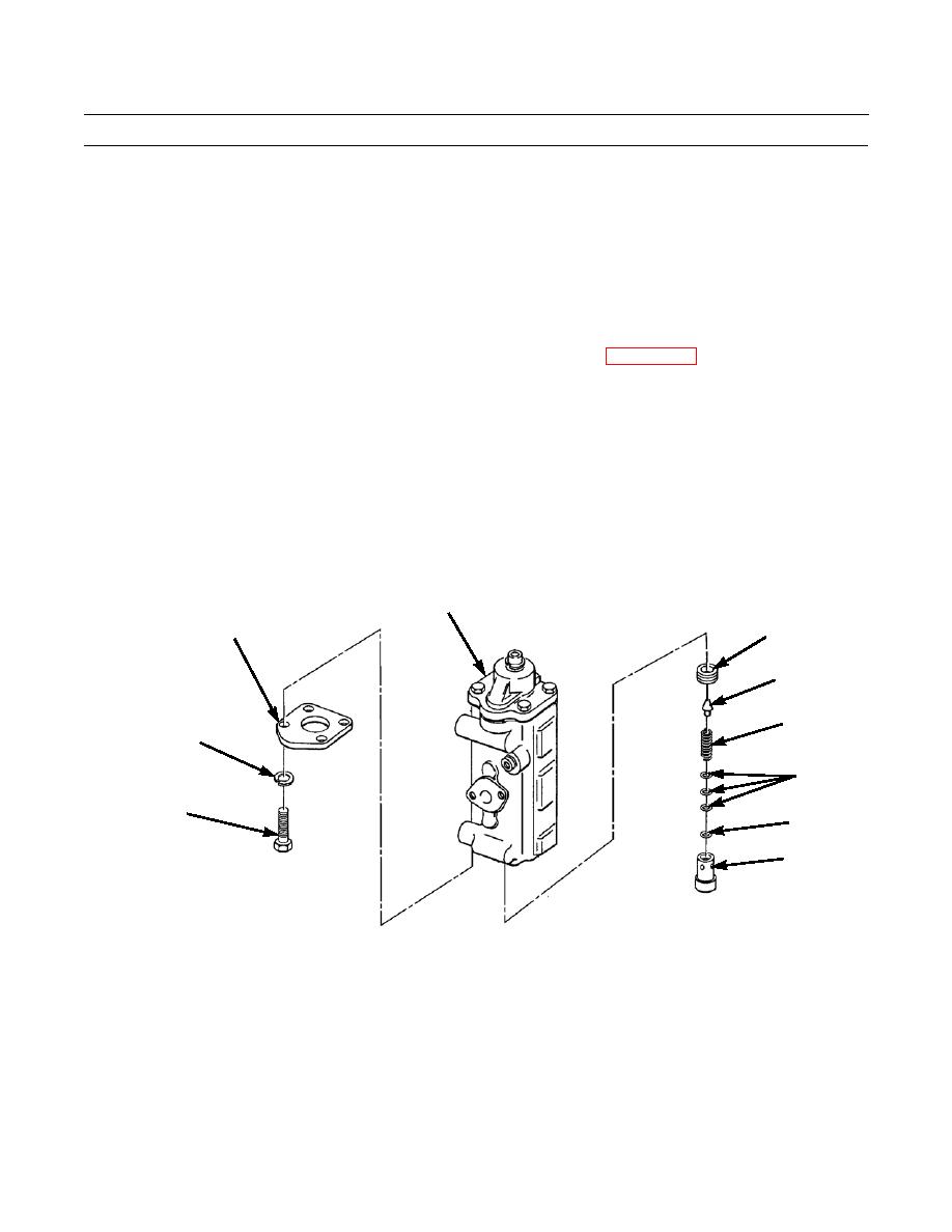
HYDRAULIC TILT CONTROL VALVE REPLACEMENT - CONTINUED
0150 00
RELIEF VALVE SETTING ADJUSTMENT - CONTINUED
2.
Remove four bolts (23), lockwashers (24) and cover (25) from tilt control valve (20). Discard lockwashers.
3.
Remove sleeve (26), spring (27), three disks (28) and pilot valve (29).
4.
Remove shims (30) from between spring (27) and sleeve (26).
NOTE
Adding one shim increases pressure by 35 PSI (2.5 kg/cm2) Removing one shim decreases pressure by the
same value.
5.
Determine number of shims (30) needed to achieve proper relief valve setting (WP 0165 00).
6.
Ensure valve seat (31) is bottomed square against shoulder in control valve body.
NOTE
Ensure spring is seated in its groove in valve seat.
7.
Install pilot valve (29), three disks (28) and spring (27).
8.
Install correct number of shims (30) as determined in step 5.
9.
Install sleeve (26).
10.
Install cover (25) with four new lockwashers (24) and bolts (23).
20
25
31
29
27
24
28
23
30
26
386-823
0150 00-5
|
|
Privacy Statement - Press Release - Copyright Information. - Contact Us |
