 |
|||
|
|
|||
|
|
|||
| ||||||||||
|
|
 TM 5-2410-233-23
STEERING BRAKE ACTUATING MECHANISM MAINTENANCE - CONTINUED
0125 00
ASSEMBLY - CONTINUED
22.
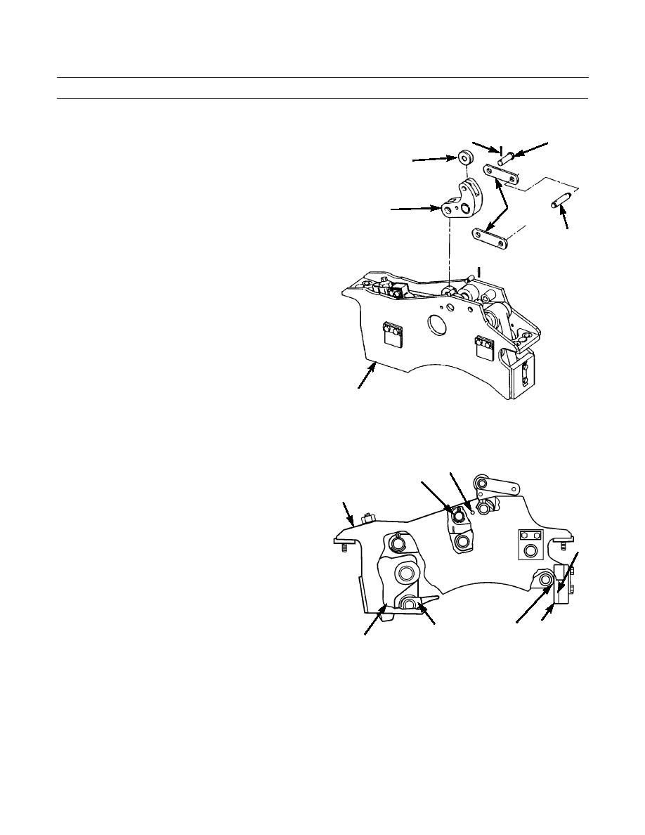
Position roller (9) in bellcrank (10).
7
8
23.
Position two links (11) on bellcrank (10) and install
9
pin (8) and new cotter pin (7).
24.
Position other ends of two links (12) in actuating
mechanism (2) and install dowel (11) through links.
12
10
11
2
386-333
25.
Adjust actuating mechanism (2) as follows:
a.
Install drift pin (63) through holes in actuating mechanism (2) and bellcrank (10).
b.
Hold lever (47) against back plate of actuating
63
mechanism (2).
10
c.
Separate struts (3) in order to remove slack in
2
linkage.
d.
Measure distance (A) between strut (3) and plate
(62) with a feeler gage. Correct distance is 0.010
+/- 0.005 in. (0.25 +/- 0.13 mm).
61
e.
Add or remove shims (61) as needed to adjust
distance (A).
A
62
3
386-339
47
0125 00-9
|
|
Privacy Statement - Press Release - Copyright Information. - Contact Us |