 |
|||
|
|
|||
|
|
|||
| ||||||||||
|
|
 TM 5-2410-233-23
STEERING BRAKE ACTUATING MECHANISM MAINTENANCE - CONTINUED
0125 00
ASSEMBLY - CONTINUED
29
30
12.
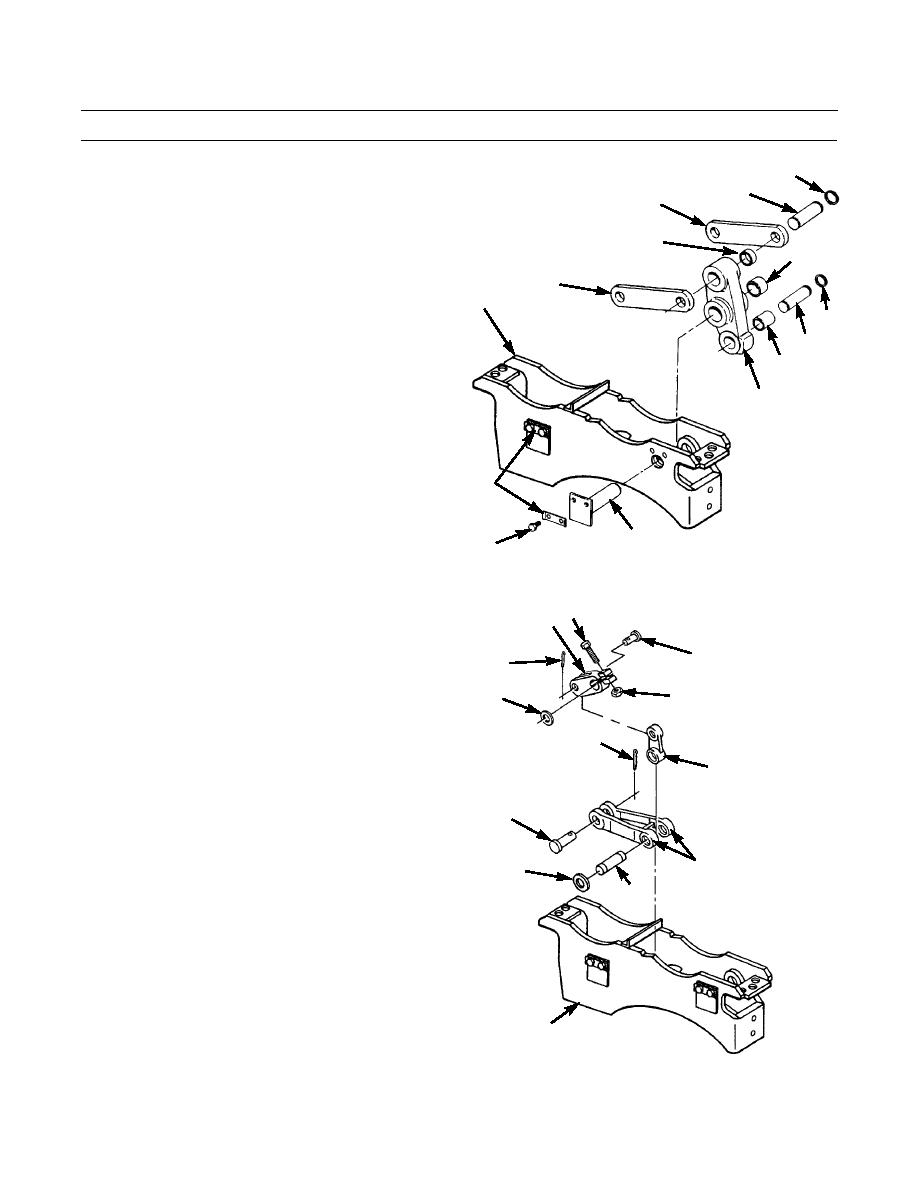
Install bearings (36, 35 and 34) in lever (28).
31
13.
Install strut (3) on lever (28) with pin (33) and retain-
ing ring (32). If removed, install other retaining ring in
36
pin.
35
14.
Install two links (31) on other end of lever (28) with
31
pin (30) and retaining ring (29). If removed, install
2
other retaining ring in pin.
32
15.
Position lever (28) and strut (3) in actuating mecha-
33
nism (2). Line up holes and insert shaft (27) through
34
actuating mechanism and lever.
16.
Install two locks (25) and capscrews (26) to secure
28
shaft (27). Bend locks.
25
27
386-335
26
17.
Install pin (21) and new cotter pin (20) in two links
15 13
(24).
18.
Install connector (19) in two links (24) and position in
17
16
actuating mechanism (2).
19.
Line up bottom hole in connector (19) with holes in
18
14
two links (24) and in actuating mechanism (2), and
insert dowel (23) and washer (22).
20
20.
Line up bottom hole in lever (15) with top hole in con-
19
nector (19) and insert pin (17) and new cotter pin (16).
21.
Install capscrew (13) and nut (14) and tighten.
21
22
24
23
2
386-334
0125 00-8
|
|
Privacy Statement - Press Release - Copyright Information. - Contact Us |