 |
|||
|
|
|||
|
|
|||
| ||||||||||
|
|
 TM 5-2410-233-23
STEERING BRAKE LOCK LEVER AND LINKAGE REPLACEMENT - CONTINUED
0124 00
INSTALLATION
1.
Position rod (14) into shaft (26) and install washer (25) and new cotter pin (24).
2.
Connect clevis (16) to lever (20) and install pin (19), washer (18) and new cotter pin (17).
3.
Install spring (13) on rod (14).
NOTE
Do not tighten adjusting nut on clevis. Adjustment is performed in step 9.
4.
Slide rod (22) through bracket (23) into lever (20).
5.
Connect rod (22) to lever (12) and install pin (21)
6.
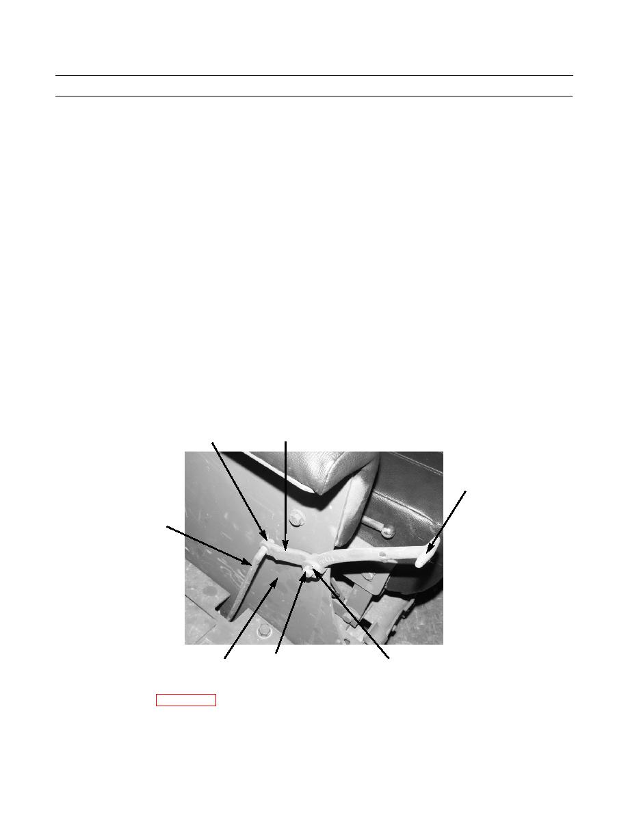
Connect rod end (3) to lever (12) with washer (11) and new cotter pin (10).
7.
Connect rod end (3) to connector (4) and install washer (2) and new cotter pin (1).
NOTE
Pin (7) may be tack welded to seat base.
8.
Install pin (7) through seat base (8) and lever (9) and install washer (6) and new cotter pin (5).
9.
Adjust rod (14) so thread measures 3/4 in. (19 mm) inside of clevis (16).
10.
Pull on lever (9) to obtain full travel of handle.
4
1,2
9
3
386-795
7
8
5,6
11.
Check steering brake lock for proper operation (TM 5-2410-233-10).
12.
Install floor plates (WP 0135 00).
END OF WORK PACKAGE
0124 00-3
|
|
Privacy Statement - Press Release - Copyright Information. - Contact Us |
