 |
|||
|
|
|||
|
|
|||
| ||||||||||
|
|
 TM 5-2410-233-23
STEERING BRAKE LOCK LEVER AND LINKAGE REPLACEMENT - CONTINUED
0124 00
REMOVAL - CONTINUED
4.
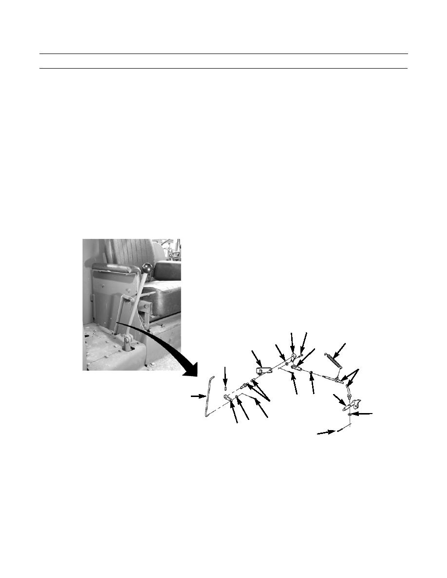
Remove cotter pin (10), washer (11) and slide rod end (3) from lever (12). Discard cotter pin.
WARNING
Spring is under tension. Wear eye protection and use extreme caution when removing spring. Failure to fol-
low this warning may result in injury to personnel.
5.
Remove spring (13) from rod (14).
NOTE
Make a mark on rod prior to loosening adjuster nut for adjustment procedure.
6.
Loosen adjusting nut (15) from clevis (16).
7.
Remove cotter pin (17), washer (18) and pin (19) and slide clevis (16) from lever (20). Discard cotter pin.
8.
Remove pin (21) and slide rod (22) through bracket (23) and from machine.
9.
Remove cotter pin (24), washer (25) and remove rod (14) from shaft (26). Discard cotter pin.
19
20
18
13
16
23
21
14
26
3
15
17
22
25
10
12 11
24
386-427
0124 00-2
|
|
Privacy Statement - Press Release - Copyright Information. - Contact Us |