 |
|||
|
|
|||
|
|
|||
| ||||||||||
|
|
 TM 5-2410-233-23
TRACK ASSEMBLY INSPECTION AND ADJUSTMENT - CONTINUED
0120 00
ADJUSTMENT - CONTINUED
7.
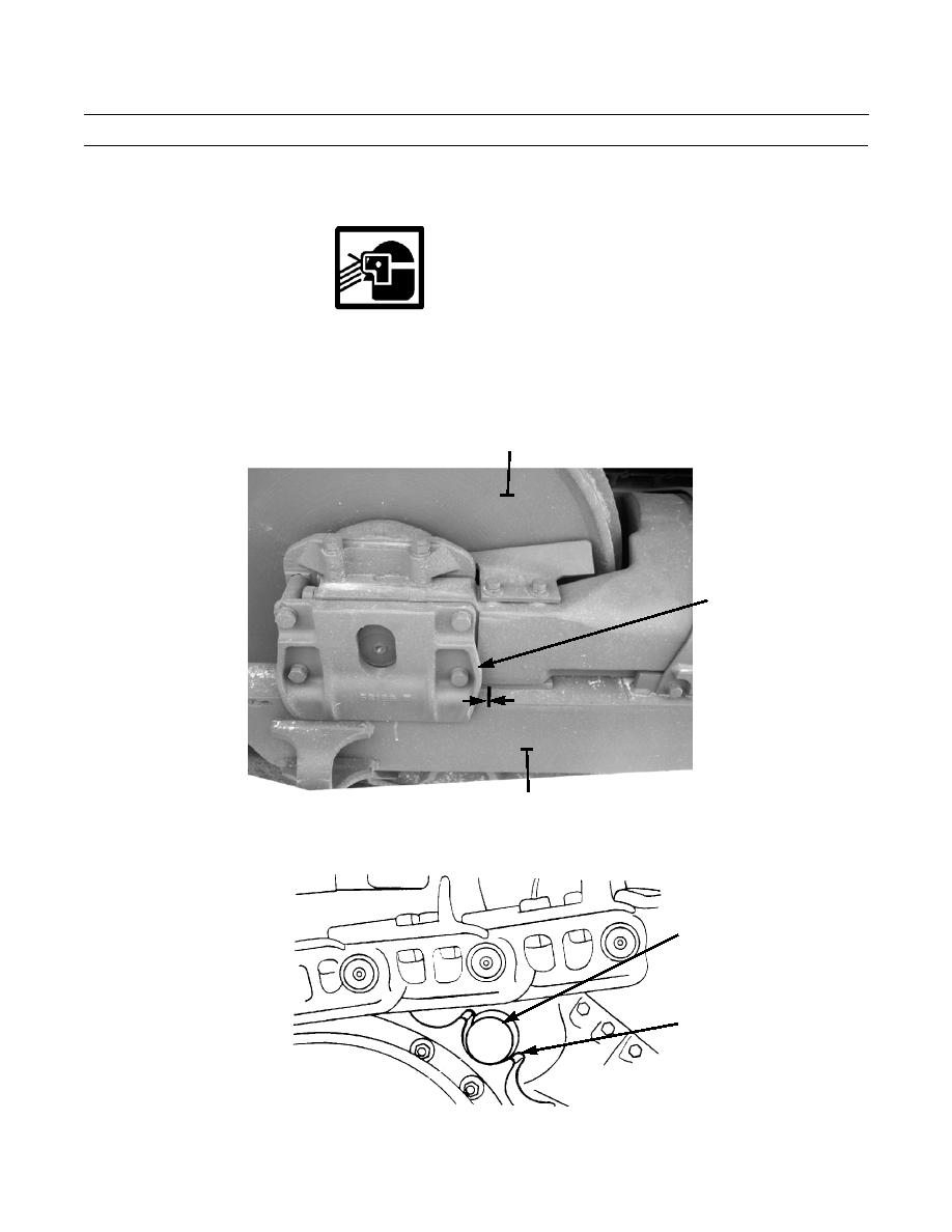
Mark a line on track roller frame (5) 1/2 in. (12.7 mm) from rear face of idler bearing support (6).
WARNING
Wear eye protection and keep face clear when venting grease from relief valve during track adjustment.
NEVER visually inspect relief valve to see if grease is escaping. Always observe track to see it has loosened.
Failure to follow this warning could cause eye injury or blindness.
8.
Open relief valve (2) no more than one turn and allow grease to escape and track idler (4) to move back.
4
6
1/2 IN. (12.7 MM)
386-716
5
9.
Put a drawbar pin (7), or a length of steel pipe, between teeth at top of track drive sprocket (8) near track link.
7
8
386-251
0120 00-6
|
|
Privacy Statement - Press Release - Copyright Information. - Contact Us |