 |
|||
|
|
|||
|
|
|||
| ||||||||||
|
|
 TM 5-2410-233-23
TRACK DRIVE SPROCKETS/HUBS REPLACEMENT - CONTINUED
0118 00
INSTALLATION - CONTINUED
6.
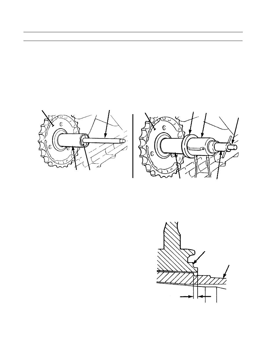
Install sleeve (47) over stud (34) and adapter (31) until it makes contact with sprocket (27).
7.
Install plate (35) on stud (34) until it makes contact with sleeve (47).
8.
Install retracted cylinder (36) on stud (34) until it makes contact with plate (35). Piston end of cylinder should face away
from sprocket (27).
9.
Install nut (41) on stud (34) to within 1 in. (2.54 cm) of cylinder (36).
10.
Connect hydraulic pump to cylinder (36) and apply 60-65 tons (534-578 kn) of pressure to force sprocket (27) fully onto
drive hub.
34
27
35
36
27
34
31
47
386-472
41
47
386-473
WARNING
Ensure pressure is off cylinder of sprocket installation tool before trying to remove tool. Failure to follow
this warning may result in injury or death to personnel.
11.
Remove sprocket installation tooling.
12.
Check distance from hub face of sprocket (27) to
spline shoulder on final drive gear hub. Dimension (A)
must be 0.500 +/- 0.060 in. (12.7 +/- 1.52 mm).
13.
If distance measured in step 12 is less than 0.44 in.
(11.18 mm), replace sprocket (27) and final drive gear
27
hub. If distance exceeds 0.560 in. (14.22 mm), remove
sprocket, clean hub splines and reinstall sprocket.
GEAR
HUB
A
386-671
0118 00-9
|
|
Privacy Statement - Press Release - Copyright Information. - Contact Us |