 |
|||
|
|
|||
|
|
|||
| ||||||||||
|
|
 TM 5-2410-233-23
TRACK DRIVE SPROCKETS/HUBS REPLACEMENT - CONTINUED
0118 00
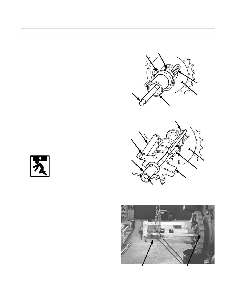
REMOVAL - CONTINUED
24.
Install stud (34) in adapter (31).
31
35
NOTE
Piston end of cylinder should face away from
sprocket.
25.
Install plate (35) and cylinder (36) on stud (34) and
against adapter (31).
32
34
27
36
386-282
26.
Install head (37) on stud (34) with flat side against cyl-
32
inder (36).
27.
Install three arms (38) to connect head (37) with
38
adapters (32) in sprocket (27) and secure arms with
39,40
pins (39) and lock pins (40) at each end.
28.
Install nut (41) on stud (34) within 1 in. (25.4 mm)
from head (37).
41
27
36
WARNING
37
Sprocket is installed with 60-65 tons (534-578
kn) of force and requires considerable force to
34
386-283
loosen. Stand clear of sprocket during loosening
procedure to avoid personal injury.
29.
Connect hydraulic pump to cylinder (36) and apply
pressure to break sprocket (27) loose. Remove hydrau-
lic pump.
386-793
27
TOOL SETUP
0118 00-5
|
|
Privacy Statement - Press Release - Copyright Information. - Contact Us |
