 |
|||
|
|
|||
|
|
|||
| ||||||||||
|
|
 TM 5-2410-233-23
TRACK ADJUSTER CYLINDER REPLACEMENT - CONTINUED
0117 00
REMOVAL - CONTINUED
3.
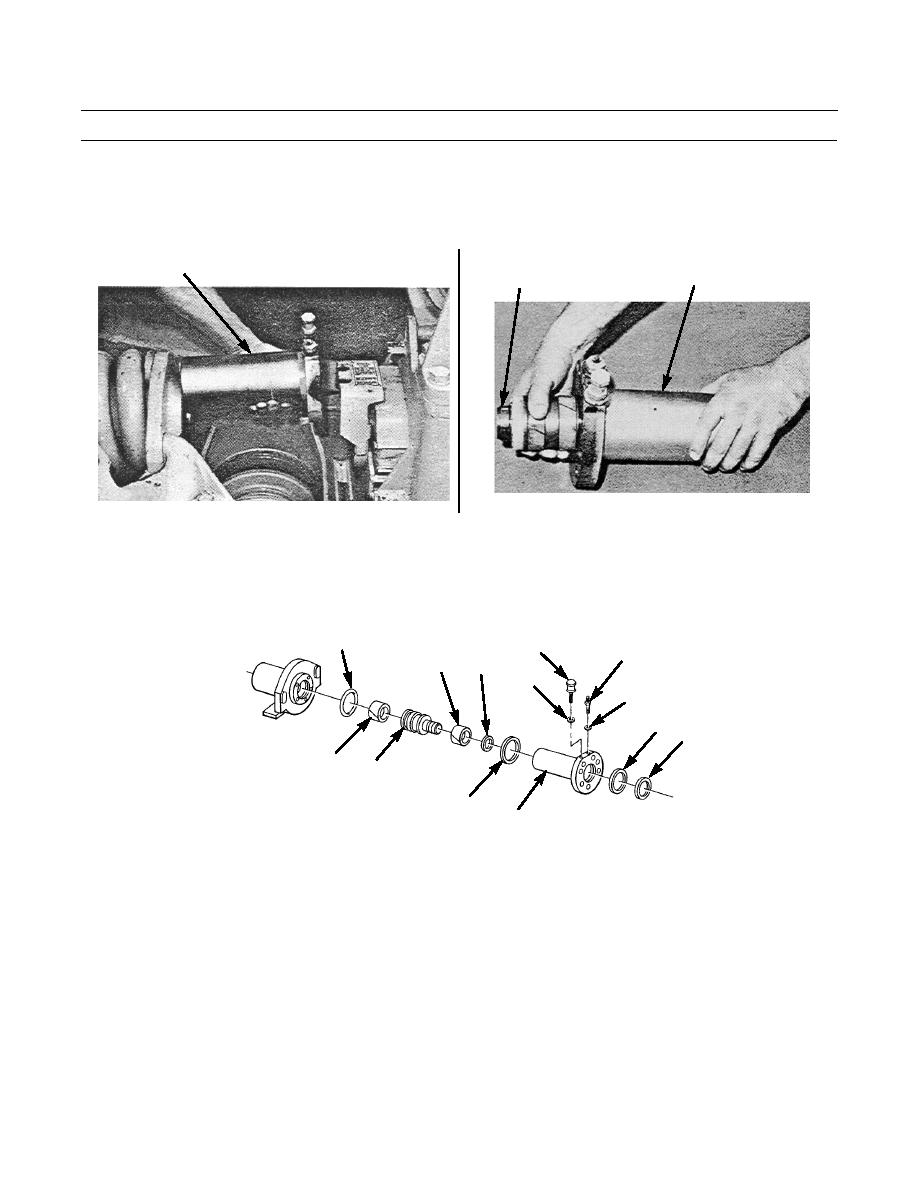
Remove adjuster cylinder (6) as a unit.
4.
Remove piston (7) as an assembly from cylinder (6) by pushing the piston out of the rear of cylinder.
6
7
6
386-037
386-036
5.
Remove seal (8) and gasket (9) from front of recoil spring. Discard seal and gasket.
6.
Remove seal (10) and ring (11) from piston (7). Discard seal.
7.
Remove ring (12), seal (13) and ring (14) from piston (7). Discard seal.
8.
Remove grease fitting (15), relief valve (16) and two washers (17) from cylinder (6).
10
16
15
14
13
17
17
8
9
11
7
12
6
386-035
INSTALLATION
1.
Install grease fitting (15), relief valve (16) and two washers (17) in cylinder (6). Tighten both valves to 25 lb-ft (34 Nm).
2.
Install ring (14) on piston (7) and new seal (13) on piston with sealing lip toward ring (12).
3.
Install ring (12) flush to secure seal (13) on piston (7).
0117 00-2
|
|
Privacy Statement - Press Release - Copyright Information. - Contact Us |
