 |
|||
|
|
|||
|
|
|||
| ||||||||||
|
|
 TM 5-2410-233-23
FINAL DRIVE PINIONS AND FLANGES MAINTENANCE - CONTINUED
0101 00
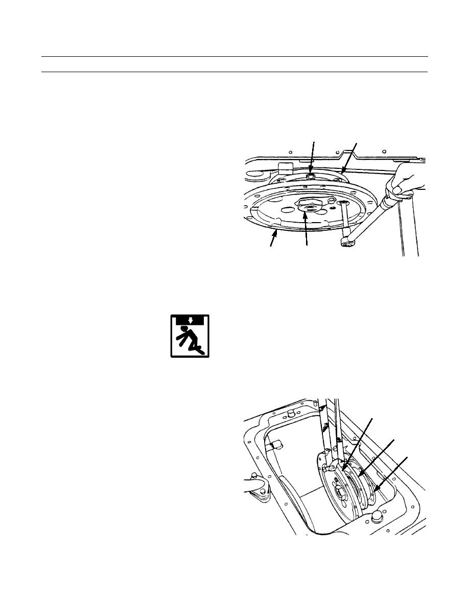
REMOVAL
NOTE
If final drive pinion and flange are to be disassembled, nut must be loosened.
1.
Wedge block of wood behind final drive flange (1) to
3,5
4
prevent it from turning. Loosen nut (2).
2.
Attach lifting equipment to track and pull track
slightly forward to align holes in final drive flange (1)
with capscrews (3) in bearing cage (4).
NOTE
Final drive flange may have to be rotated
slightly to gain access to some capscrews.
3.
Remove seven capscrews (3) and washers (5) from
bearing cage (4).
2
1
386-543
4.
Rotate flange (1) enough to align holes in flange with forcing screw holes in bearing cage (4) and install two 3/8 -16NC
forcing screws in bearing cage.
5.
Turn forcing screws evenly until bearing cage (4) is free of bevel gear case.
WARNING
Use extreme caution when handling heavy parts. Provide adequate support and use assistance during pro-
cedure. Ensure that any lifting device used is in good condition and of suitable load capacity. Keep clear of
heavy parts supported only by lifting device. Failure to follow this warning may result in injury.
NOTE
1
Weight of final drive pinion and flange as a unit
is 80 lb (36 kg).
6.
Attach a nylon sling and a suitable lifting device to
4
final drive pinion (6) and flange (1) as a unit and
6
remove from gear case.
386-544
0101 00-2
|
|
Privacy Statement - Press Release - Copyright Information. - Contact Us |
