 |
|||
|
|
|||
|
|
|||
| ||||||||||
|
|
 TM 5-2410-233-23
0100 00
INSTALLATION - CONTINUED
NOTE
Weight of hub is 218 lb (99 kg).
10.
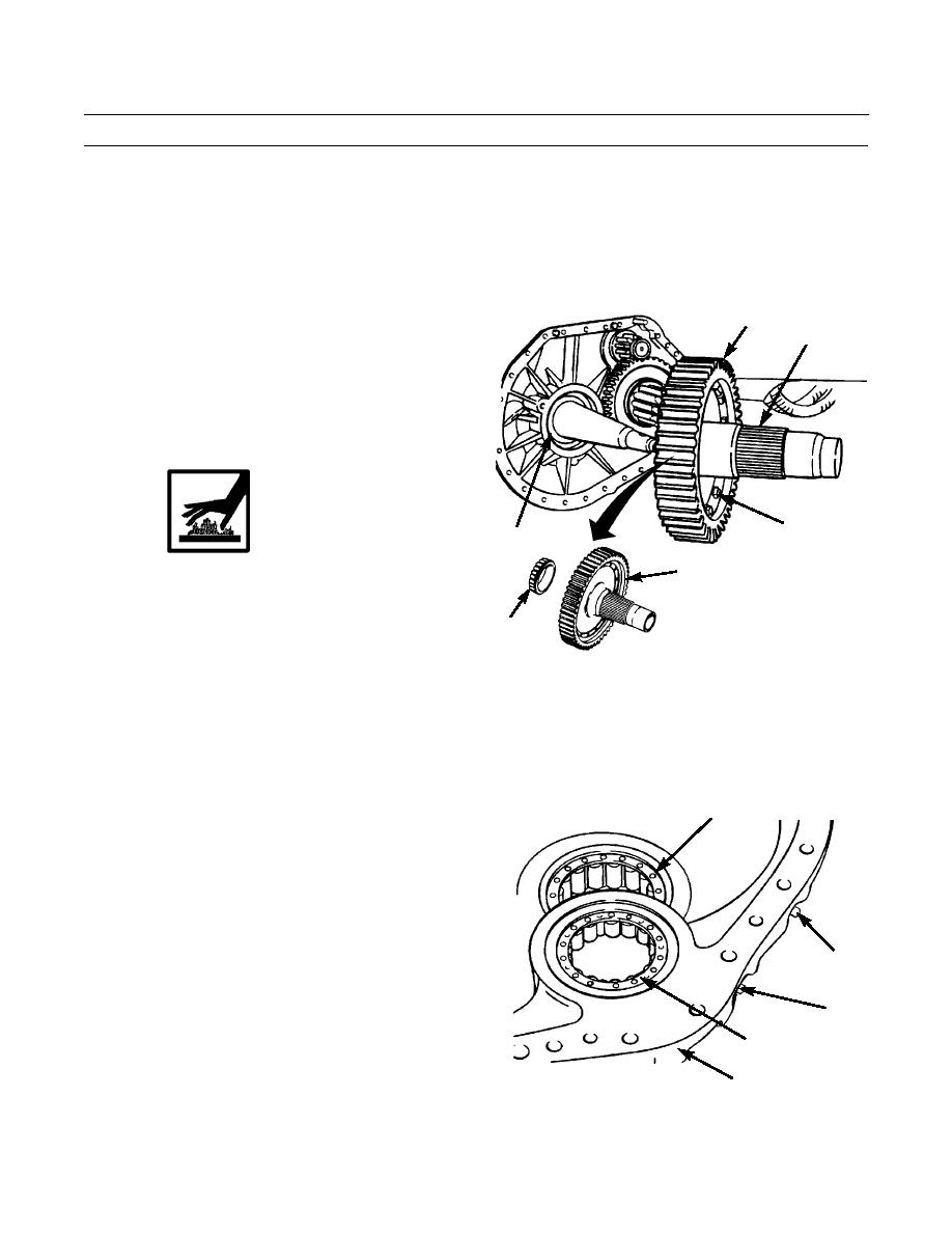
Attach lifting device to hub (13) and put it in position
in gear (12) with long neck side of hub up.
12
11.
Install 15 bolts (15) through hub (13) and gear (12)
13
and secure with eight new locks (18) and 15 nuts (14).
Bend locks up against flats of bolt heads.
12.
Attach a lifting link to hole in gear (12). Attach a
nylon sling to lifting link and to a suitable lifting
device. Turn assembly over and position it on blocks
with long neck side of hub (13) down.
14,15,18
WARNING
19
Wear hand protection when handling hot com-
12
ponents to prevent burns.
13.
Heat bearing cone (17) to a maximum temperature of
17
275F (135C). Install bearing cone on hub (13).
14.
If removed, install bearing cup (19).
386-542
NOTE
Weight of gear and hub is approximately 350 lb (159 kg).
15.
Install key (16). Use lifting link, nylon strap and lifting device to put gear (12) and hub (13) part way onto sprocket
shaft. Remove lifting link, nylon sling and lifting device.
16.
Install one remaining bolt (15) and nut (14). Bend
8
remaining tab of one lock (18) against bolt head.
17.
Push gear (12) and hub (13) fully onto sprocket shaft.
18.
Lower temperature of race and roller assemblies (7
and 8). Install race and roller assemblies in final drive
case (3) with dowel hole in race and roller assemblies
in line with dowel hole in final drive case.
19.
Use a 1/4 in. -20NC capscrew to install dowel (11) for
9,11
race and roller assembly (8). Remove capscrew.
20.
Use a #10 - 32 screw to install dowel (10) for race and
9,10
roller assembly (7). Remove screw.
21.
Install two new plugs (9) in dowel holes in drive case
7
(3).
386-534
3
22.
Apply gasket compound on contact surfaces of steer-
ing clutch case and final drive case (3).
0100 00-9
|
|
Privacy Statement - Press Release - Copyright Information. - Contact Us |