 |
|||
|
|
|||
|
|
|||
| ||||||||||
|
|
 TM 5-2410-233-23
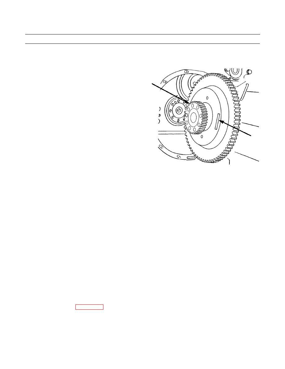
FLYWHEEL ASSEMBLY REPLACEMENT - CONTINUED
0028 00
REMOVAL - CONTINUED
7.
Apply witness marks on hydraulic pump gear (4) and
flywheel assembly (3) with paint or scribe.
8.
Remove hydraulic pump gear (4) from back of fly-
4
wheel assembly (3).
3
386-197
I
NSTALLATION
1.
Align witness marks on flywheel assembly (3) and hydraulic pump gear (4) and install gear on flywheel assembly.
NOTE
Flywheel assembly weighs 125 lb (57 kg).
2.
Fasten lifting equipment to flywheel assembly (3).
3.
Lift flywheel assembly (3) into place on two 5/8 in.-18NF guide bolts installed into crankshaft.
4.
Align dash marks on flywheel assembly (3) and crankshaft and push flywheel assembly further in on guide bolts.
5.
Remove lifting equipment from flywheel assembly (3).
6.
Push flywheel assembly (3) all the way in against rear of crankshaft.
7.
Install seven washers (2) and capscrews (1).
8.
Remove 5/8 in. -18NF guide bolts from crankshaft.
9.
Install two remaining washers (2) and capscrews (1). Tighten nine capscrews to 150 lb-ft (203 Nm).
10.
Install torque divider (WP 0092 00).
11.
Run engine and check for proper operation (TM 5-2410-233-10).
END OF WORK PACKAGE
0028 00-3
|
|
Privacy Statement - Press Release - Copyright Information. - Contact Us |
