 |
|||
|
|
|||
|
|
|||
| ||||||||||
|
|
 TM 5-2410-233-23
ENGINE ASSEMBLY REPLACEMENT - CONTINUED
0019 00
INSTALLATION - CONTINUED
14.
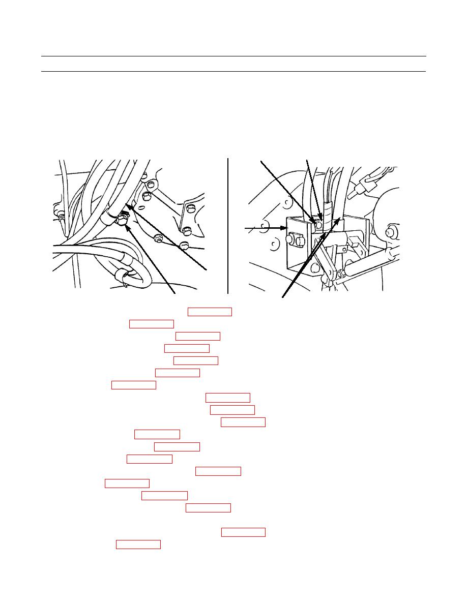
Position battery cable (7) over flywheel housing and attach clamp to flywheel housing with flatwasher (6) and capscrew
(5).
15.
Position power cables (3) through governor control linkage bracket (4).
16.
Attach clip (2) holding power cables (3) to bracket (4) and secure with capscrew (1).
2
1
4
7
386-172
386-171
5,6
3
17.
Install torque converter outlet relief valve (WP 0096 00).
18.
Install hydraulic pump (WP 0148 00).
19.
Install winch gear pump (if equipped) (WP 0147 00).
20.
Connect NATO starting receptacle (WP 0082 00).
21.
Connect steering clutch control lever (WP 0123 00).
22.
Connect steering brake linkage (WP 0121 00).
23.
Install driveshaft (WP 0106 00).
24.
Connect transmission oil lines to torque divider (WP 0097 00).
25.
Connect transmission vent line and oil outlet line (WP 0088 00).
26.
Connect transmission inlet and outlet oil cooler lines (WP 0087 00).
27.
Connect alternator wires (WP 0070 00).
28.
Connect starter solenoid cables (WP 0072 00).
29.
Connect starter cables (WP 0071 00).
30.
Connect governor control linkage and adjust (WP 0054 00).
31.
Install radiator (WP 0063 00).
32.
Connect water pump hoses (WP 0066 00).
33.
Connect water pressure gage sensing line (WP 0063 00).
34.
Replace any removed tiedown straps with new. Secure any loose tubes, hoses or wiring with new tiedown straps.
35.
Close crankcase and transmission guards, if required (WP 0129 00).
36.
Install floor plates (WP 0135 00).
0019 00-9
|
|
Privacy Statement - Press Release - Copyright Information. - Contact Us |