 |
|||
|
|
|||
|
Page Title:
LOCATING TOP DEAD CENTER (TDC) COMPRESSION STROKE FOR NUMBER 1 PISTON (Cont) |
|
||
| ||||||||||
|
|
 TM 5-2410-233-23
VALVE MECHANISM ADJUSTMENT- CONTINUED
0017 00
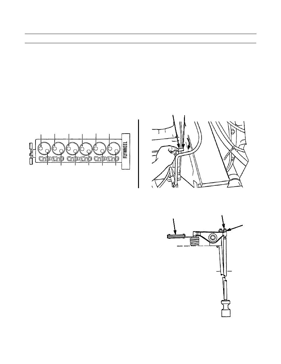
LOCATING TOP DEAD CENTER (TDC) COMPRESSION STROKE FOR NUMBER 1 PISTON - CONTINUED
NOTE
If piston is on compression stroke, valves will be closed on number 1 cylinder.
3.
Try moving rocker arms over cylinder number 1 up and down. If arms do not move, valves are open and piston is not on
compression stroke. Proceed to step 4.
4.
Remove bolt (25) and turn flywheel 360 degrees to the right. Return bolt to hole (26). Number 1 piston is now at TDC
on compression stroke.
26
25
EXHAUST VALVES
3
2
5
6
4
1
1
2
5
4
3
6
386-163
INTAKE VALVES
CYLINDER AND VALVE IDENTIFICATION
386-164
ADJUSTING VALVE CLEARANCE
28
FEELER GAGE
NOTE
27
Ensure pushrods are not bent before
performing adjustment.
When valve clearance is checked
using a feeler gage, it is NOT NECES-
SARY to adjust valves if measure-
ment falls within 0.022-0.028 in.
(0.56-0.71 mm) for exhaust and
within 0.012-0.018 in. (0.30-0.46 mm)
for intake.
1.
Loosen nut (27). Make adjustment to each valve by
using a flat-tipped screwdriver and turning adjustment
screw (28) to obtain correct reading with feeler gage.
2.
After adjustment for each valve has been made,
386-165
tighten nut (27) for valve adjustment screw (28) to 22
lb-ft (30 Nm), while holding screw.
0017 00-7
|
|
Privacy Statement - Press Release - Copyright Information. - Contact Us |
