 |
|||
|
|
|||
|
|
|||
| ||||||||||
|
|
 TM 10-3930-633-34
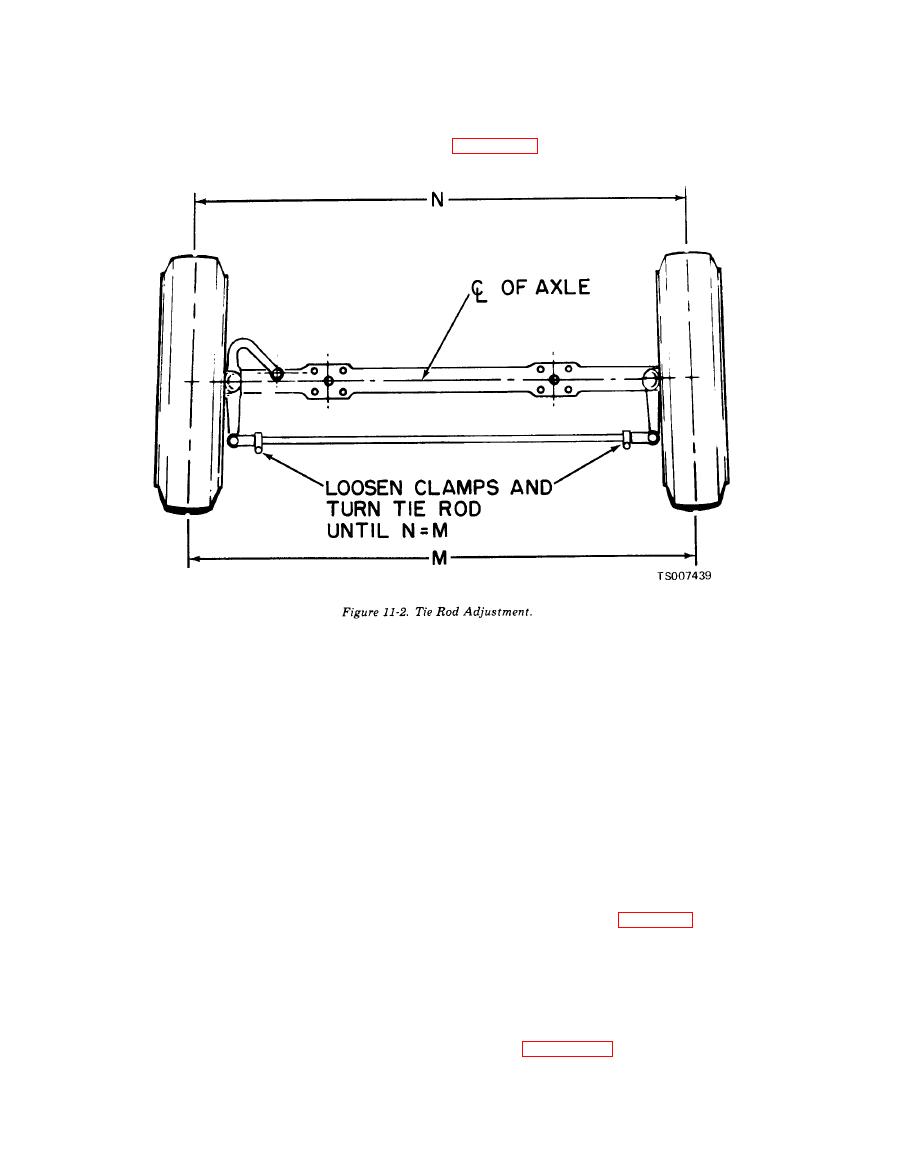
(3) Actual toe-in measurements should be
(2) Check the toe-in of front wheels after
taken at hub-height, between the two points on
rolling the truck ahead one full revolution of the
the center of the tread at the rear of the tires. See
wheels (with only the weight of the truck on the
--
tires).
(3) Clean all parts in solvent, Federal
(4) Mark the point and roll the truck ahead
Specification P-D -680.
so that the points are in the front at hub-height
(4) Check for cracks, dents, corrosion, and in
and measure the distance between the same two
particular, wear and damaged threads. Replace
points on the tire treads.
all worn or defective parts.
(5) The difference in the two measurements
(5) Reassemble clamps on tie rod tube and
is the actual toe-in or toe-out.
install tie rod ends. Do not tighten clamps, as tie
(6) To adjust the toe-in, turn the steering
rod ends will have to be adjusted at assembly
wheel so that the gear is in the mid-position.
with axle.
(7) Loosen the clamping bolts on the ends of
d. Installation. Install tie rod to front axle,
the tie rod.
and secure ball studs in steering arms by in-
(8) Rotate the tie rod in the direction
stalling castellated nut and cotter pins. Adjust
necessary to bring toe-in within the specified
toe-in as outlined in subparagraph a. Lubricate in
range (zero).
(9) Tighten the clamp bolts on the tie rod
accordance with LO 10-3930-633-12.
ends.
11-3. Steering Gear
b. Removal. The tie rod is secured to the axle
a. Removal. Refer to Chapter 2, Section IV, for
at each end by a nut and cotter pin on the end of
complete removal procedures.
each ball stud. To remove the tie rod, remove
b. Disassembly.
cotter pins and nuts and tap the ball stud ends
NOTE
free of the steering arms.
As with any ball bearing unit, the steering gear parts
c. Disassembly, Repair and Reassembly.
must be kept free of dirt. Clean paper or rags should
be spread on the bench before starting disassembly of
(1) Loosen clamps on each tie rod end, and
the steering gear.
unscrew and remove the tie rod ends from the
Refer to figure 11-3 for parts identification and
tube.
proceed as follows:
(2) Remove clamp and clamp bolts.
|
|
Privacy Statement - Press Release - Copyright Information. - Contact Us |
