 |
|||
|
|
|||
|
Page Title:
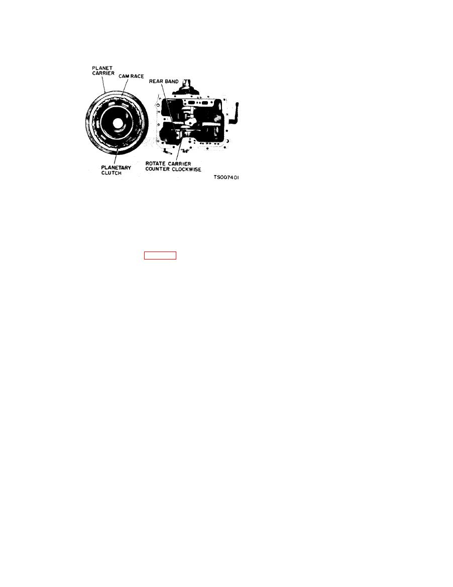
Figure 7-13. Planetary Clutch Installation. |
|
||
| ||||||||||
|
|
 TM 10-3930-633-34
(17) Install the governor assembly, aligning
the groove with the ball in the output shaft.
(18) Install the governor with the governor
body plate toward the rear of the transmission.
Install the governor snap ring.
(19) Place the four seal rings in the
distributor sleeve, and check the ring gap.
(20) Check the fit of the seal rings in the
grooves in the output shaft. The rings should
rotate freely. Install the rings in the grooves of
the output shaft.
(21) Install the three tubes in the distributor
sleeve.
(22) Install the distributor sleeve on the
output shaft, wit h the chamfer facing forward.
.
Lubricate the parts to facilitate assembly. Slide
the sleeve over the four rings and at the same time
(8) Carefully position the planet carrier on
start the tubes into the case. The distributor
the center support. Move the carrier forward until
sleeve is located between the governor snap ring
the clutch rollers are felt to contact the bearing
and speedometer drive gear.
surface of the center support.
(23) Make sure that the speedometer drive
(9) While applying forward pressure on the
gear lock ball is in place, then install the gear.
planet carrier, rotate it counterclockwise, as
(24) Install the output shaft ball bearing
viewed from the rear (fig. 7-13). This will cause
front spacer and the output shaft ball bearing
the clutch rollers to roll toward the large opening
with the snap ring toward the rear,
end of the cams in the race, compressing the
(25) Install the output shaft rear spacer and
spring slightly, so that the rollers will ride up the
the speedometer drive gear.
chamfer on the planetary support and onto the
(26) Install the rear bearing retainer gasket
inner race.
and the retainer. Torque the bolts to specifi-
(10) Push the planet carrier all the way
cations.
forward.
(27) Install the brake drum and companion
(11) Check the operation of the planetary
flange. Torque the nut to 150-200 ft/lb. Tighten
clutch by rotating the carrier counterclockwise. It
the nut to the nearest cotter pin hole, and install
should rotate counterclockwise (viewed from the
the cotter pin.
rear) with a slight drag, and it should lock up
(28) Position a new front pump gasket in the
when attempting to rotate it in a clockwise
counterbore of the transmission case.
direction.
(29) Install the front pump, aligning the
(12) Install the selective thrust washer on
pump bolt holes with the holes in the case. Install
the pinion carrier rear pilot. If the end play was
three of the front pump attaching bolts and
not within specifications when checked prior to
torque them to 17-22 ft/lb.
disassembly, replace the washer with one of
(30) Mount dial indicator support in a front
proper thickness. Refer to TM 10-3930-633-34P
pump bolt hole. Mount a dial indicator on the
for selective thrust washer thicknesses.
support so that the contact rests on the end of
(13) Install the output shaft, carefully
turbine shaft.
meshing the internal gear with the pinions.
(31) Pry the output shaft all the way forward
( 1 4 ) With the center support properly
by using a screwdriver between the large internal
assembled, position the rear pump drive key in
gear and the case.
the keyway on the output shaft.
(32) Lightly block the output shaft in the
(15) Position new front and rear gaskets on
forward position to eliminate all output shaft end
the pump body. Retain the gaskets with trans-
play.
mission fluid. Then install the rear pump. Be
(33) Move the pinion carrier all the way
sure the drive key is aligned with the keyway in
forward by inserting a screwdriver between the
the pump drive gear.
planet carrier and the large internal gear and
(16) Position the governor drive ball in the
prying against the case. Maintain slight forward
pocket in the output shaft. Retain the ball with
pressure, and set the dial indicator at zero.
transmission fluid.
|
|
Privacy Statement - Press Release - Copyright Information. - Contact Us |
