 |
|||
|
|
|||
|
Page Title:
Section VI. PISTONS, PINS, AND RINGS |
|
||
| ||||||||||
|
|
 TM 10-3930-633-34
(3) It is imperative to pull the plug into the
(4) Oversize (OS) plugs are identified by the
machined bore by using a properly designed tool.
OS stamped in the flat located on the cup side of
Under no circumstances is the plug to be driven
the plug.
into the bore using a tool that contacts the flange.
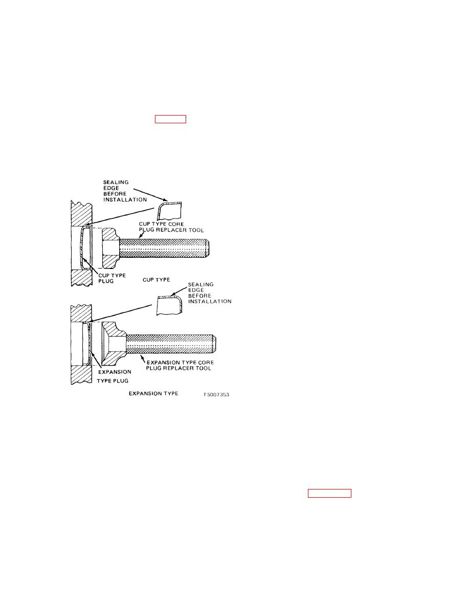
b. Installation (Cup Type).
This method will damage the sealing edge and will
(1) Coat the plug and bore lightly with an oil
result in leakage and/or plug blow out.
resistant or water resistant sealer and install as
(4) The flanged (tailing) edge must be below
follows :
the chamfered edge of the bore to effectively seal
(2) Cup type core plugs (fig. 6-24) are in-
the plugged bore.
stalled with the flanged edge outward. The
maximum diameter of this plug is located at the
(5) If the core plug replacing tool has a depth
seating surface, do not seat the tool against a
outer edge of the flange. The flange on cup type
non-machined (casting) surface.
plugs flares outward with the largest diameter at
c. Installation ( Expansion Type ).
the outer (sealing) edge.
(1) Expansion type core plugs are installed
with the flanged edge inward. The maximum
diameter of this plug is located at the base of the
flange with the flange flaring inward.
(2) It is imperative to push or drive the plug
into the machined bore using a properly designed
tool, Under no circumstances is the plug to be
driven using a tool that contacts the crowned
portion of the plug. This method will expand the
plug prior to installation and may damage the
plug and/or plug bore.
(3) When installed the trailing (maximum)
diameter must be below the chamfered edge of the
bore to effectively seal the plugged bore.
(4) If the core plug replacing tool has a depth
seating surface, do not seat the tool against a cast
surface.
Section VI. PISTONS, PINS, AND RINGS
caustic cleaning solution or a wire brush to clean
a. Cleaning.
(2) Clean the ring groove with a ring groove
(1) Remove deposits from the piston sur-
cleaner (see figure 6-25). Make sure the oil ring
faces. Clean gum or varnish from the piston skirt,
slots are clean.
piston pins and rings with solvent. Do not use a
|
|
Privacy Statement - Press Release - Copyright Information. - Contact Us |