 |
|||
|
|
|||
|
Page Title:
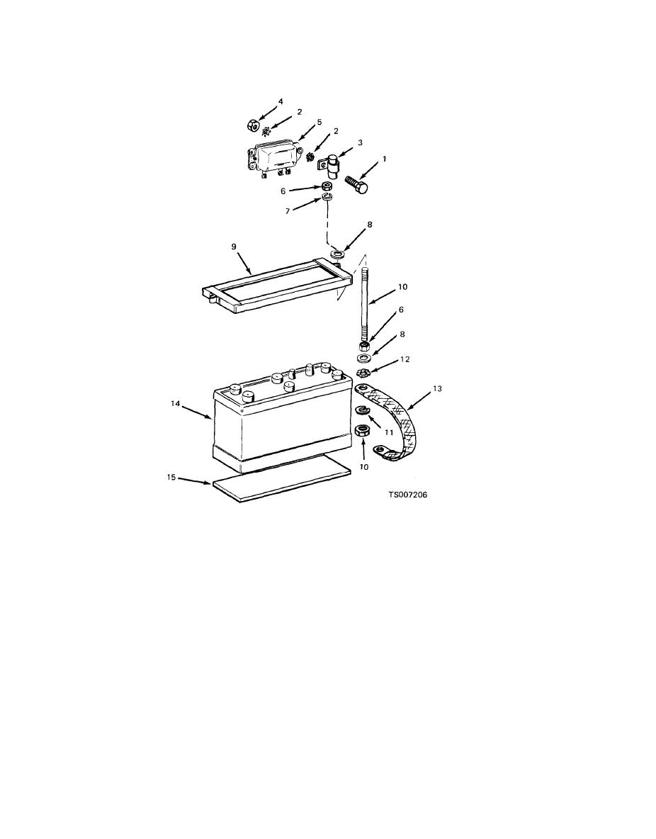
Figure 4-17. Battery and Regulator Mounting |
|
||
| ||||||||||
|
|
 TM 10-3930-633-12
1. Screw
6.
Nut
11.
Lockwasher
2. Washer
7.
Washer
12.
Washer
3. Capacitor
8.
Washer
13.
Ground strap
4. Nut
9.
Hold-down frame
14.
Battery
5. Voltage regulator
10.
Stud
15.
Cushion
(2) Meters and gages can be tested by
If testing of our troubleshooting the electrical
(temperature and fuel level gages), ammeter or
system indicates the cause of an abnormal gage
voltmeter. The temperature and fuel level gages
reading or system malfunction to be in the in-
operate on a variable resistance principle; the
strument or switch rather than elsewhere in the
ohmmeter will measure the resistance through
circuit, the defective gage or switch will have to
the sending unit. If resistance is infinite, the
be replaced.
sender may be faulty or wiring broken.
a. Testing.
(3) Inspect meters and gages for cracked
(1) Faulty light or ignition switches can be
glass, illegible dial faces, damaged terminals,
tested by bridging the switch terminals with a
faulty movements, and other damage.
jumper wire, If circuit then operates normally,
(4) Inspect switches for rough, catching, or
the switch is faulty.
|
|
Privacy Statement - Press Release - Copyright Information. - Contact Us |
