 |
|||
|
|
|||
|
|
|||
| ||||||||||
|
|
 TM 9-2320-364-20-1
Allow engine to cool before performing troubleshooting maintenance. If necessary use insulated pads
and gloves. Hot engine components will burn and cause personnel injury.
Do not use any other procedures in this manual (except for the suggestions listed below and Fault
steps) when trying to solve an intermittent problem. Use of any other procedures for this kind of
problem CAN result in the replacement of non-defective parts. Many intermittent problems are
caused by faulty electrical connectors or wiring. Diagnosis must include a careful inspection of
the indicated wiring and connectors. Example: an intermittent Code 35 (Oil Pressure Sensor Voltage High)
should cause suspicion of a problem in the following areas associated with the Oil Pressure Sensor.
1. Wire 530 (signal line), Wire 416 (+5 volt line) or Wire 452 (ground line).
2. The Oil Pressure Sensor connector or DDEC ECM connector.
3. An intermittent in the Oil Pressure Sensor (least likely).
DDEC ECM connector terminals are easily damaged. Use care when connecting and disconnecting
connectors.
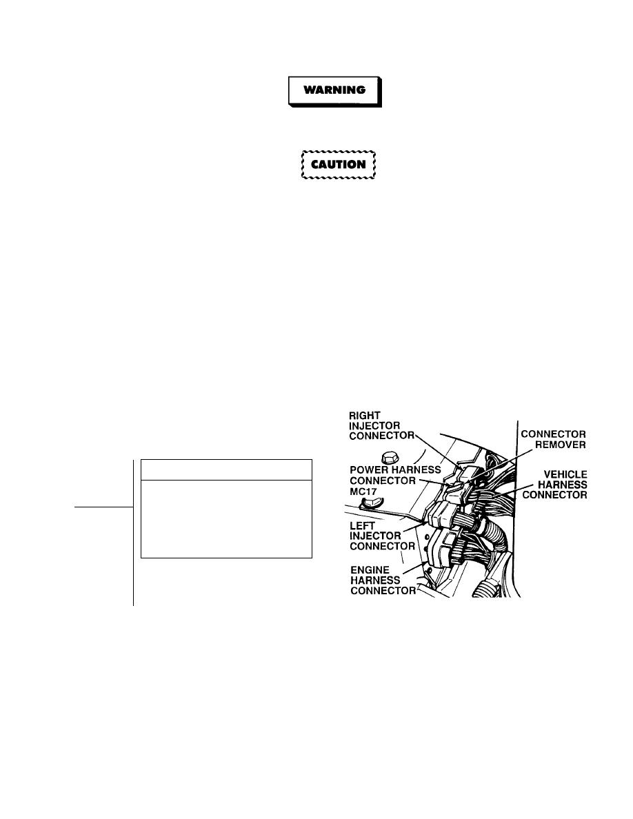
NOTE
The following steps should only be
used if troubleshooting was started
at DDEC II Troubleshooting (All
Conditions) and you were referred here.
VISUAL INSPECTION
Inspect all DDEC ECM connectors for
proper alignment and seating.
(1) If connectors are not seated
properly, reseat and go to Step 2
of this Fault.
(2) If connectors are seated properly,
go to Step 2 of this Fault.
|
|
Privacy Statement - Press Release - Copyright Information. - Contact Us |
