 |
|||
|
|
|||
|
Page Title:
Table 2-17. Injector Identification |
|
||
| ||||||||||
|
|
 TM 9-2320-364-20-1
NOTE
The following steps should only be
used if troubleshooting was started
at DDEC II Troubleshooting (All
Conditions) and you were referred here.
Table 2-17 shows which injector is
associated with each of the failure codes.
Troubleshooting procedures for codes 71
through 78 are the same for codes 61
through 68.
Firing
Code
Cylinder
Order
61
1
1 Left
62
2
3 Right
63
3
3 Left
64
4
4 Right
65
5
4 Left
66
6
2 Right
67
7
2 Left
68
8
1 Right
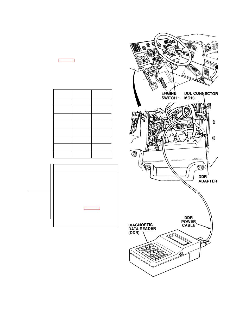
DDR TEST
(1) Connect DDR to DDL connector
MC13.
(2) Turn ON ENGINE switch
(TM 9-2320-364-10).
(3) Select MODE 01 (ACTIVE CODES)
on DDR.
(a) If Code(s) 61 through 68 are not
the only codes displayed, turn
OFF ENGINE switch and go to
Fault Index (Table 2-16).
(b) If Code(s) 61 through 68 are the
only code(s) displayed, turn OFF
ENGINE switch and go to Step 2
of this fault.
2-355
|
|
Privacy Statement - Press Release - Copyright Information. - Contact Us |
